
Current collector for lead acid battery

a lead acid battery and collector technology, applied in the field of batteries, can solve the problems of shortening the cycle life of current commercial lead acid batteries, and achieve the effects of long cycle life, high specific energy, and low cos

Inactive Publication Date: 2011-11-10
WANG XIAOGANG
View PDF10 Cites 23 Cited by
  • Summary
  • Abstract
  • Description
  • Claims
  • Application Information

AI Technical Summary

Benefits of technology

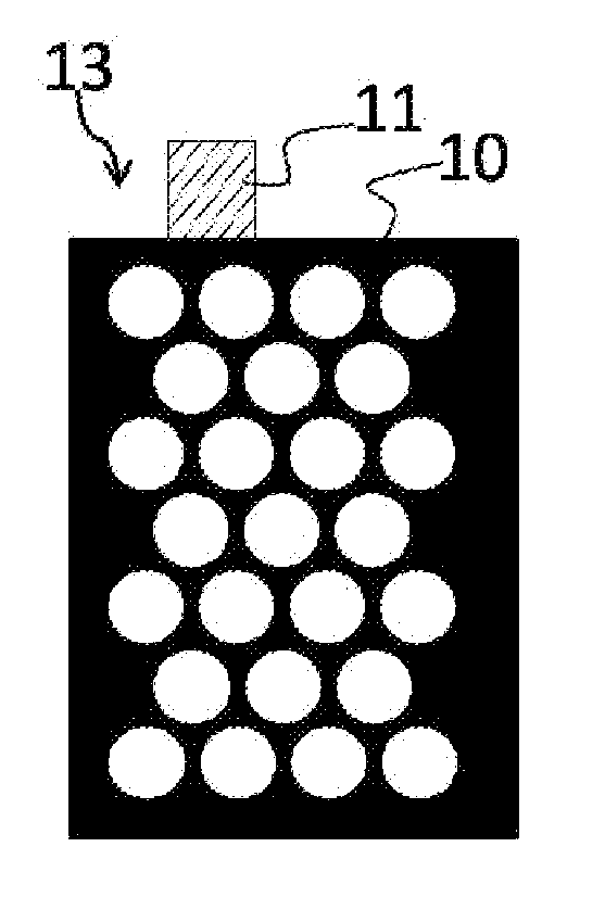
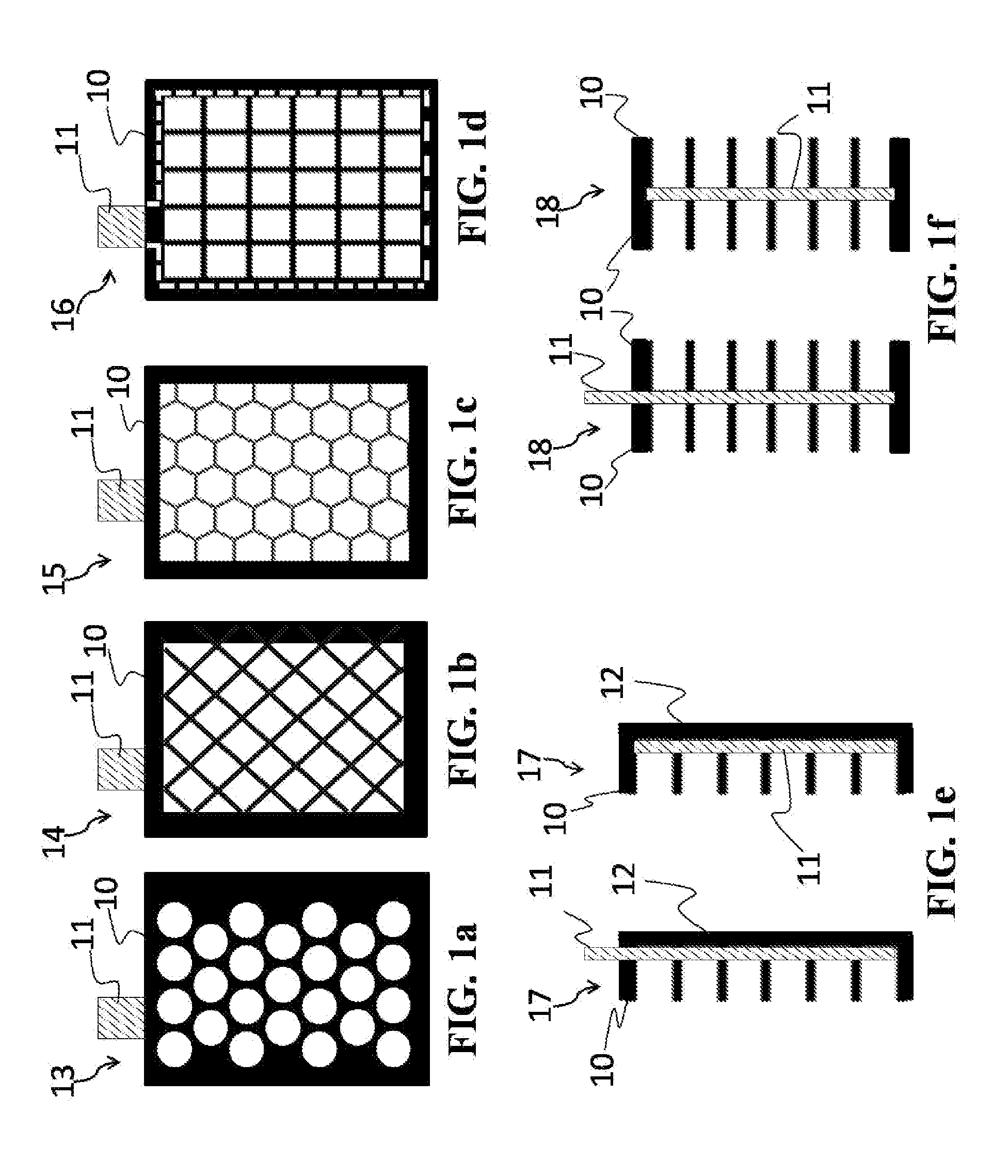
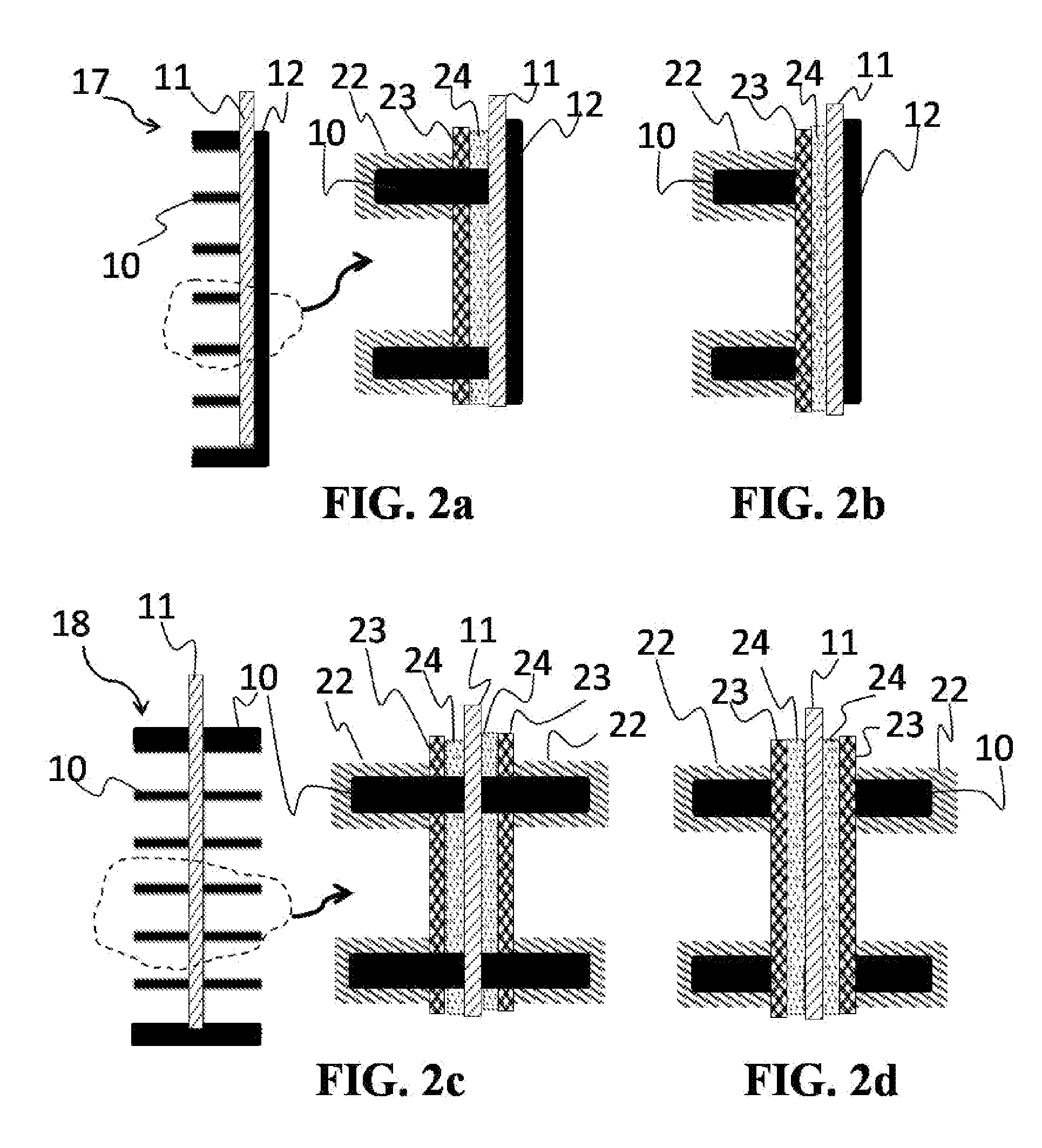
The present invention provides new lead acid batteries for EV, HEV, PHEV, and other applications. The batteries have a low cost, high specific energy, and long cycle life. The current collector in the battery has a high weight rate of active materials and increases the relative weight rate of active materials, which greatly increases the specific energy. The current collector also optimizes the ratio of interface area to active materials, which increases the utilization of active materials and then increases the specific energy. The long cycle life means that the battery can be used for a longer time. The special bonding layers on the current collector surfaces achieve good adhesion between the current collector and active materials, and the structure of the current collector holds the active materials well. The lead acid batteries are highly resistant to vibration damage and have good mechanical properties. The ratio of the contact area between the grid / current collector system and active materials to volume of active materials is maximized, which makes the battery charge much faster than current commercial lead acid batteries.

Problems solved by technology

Such corrosion and sulfation greatly shorten the cycle life of current commercial lead acid batteries.

Method used


Image

  • Current collector for lead acid battery
  • Current collector for lead acid battery
  • Current collector for lead acid battery

Examples


example 1

[0041]A 2 V lead acid battery was built according to the monopolar configuration as shown in FIG. 4a. The grid structure, polycarbonate, and aluminum foil were chosen to make the current collector. The porous polymer was chosen as the separator.

[0042]FIG. 5 shows the discharge characteristics of this battery at different charged times. The battery was discharging at 21° C. The charge is fast. 5 minutes can be charged to about 48% of the capacity, and 10 minutes to about 60% of the capacity. The battery can be fully charged in less than 2 hours. The utilization rate of the active materials was estimated based on experimental data, and is about 60%. The specific energy of this battery can be approximately calculated, and is about 83 Wh / kg. Cycle tests have been performed for more than three months and are ongoing, and results indicate that the change of the performance of the battery after more than 160 cycles is negligible.

example 2

[0043]A 6 V lead acid battery is built according to the bipolar configuration as shown in FIG. 4b. The grid structure, polycarbonate, and aluminum foil were chosen to make the current collector. The porous polymer was chosen as the separator.

[0044]FIG. 6 shows the discharge characteristics of this battery at different charged times. The battery was discharging at 21° C. The charge is fast. 5 minutes can be charged to about 51% of the capacity. The battery can be fully charged in less than 2 hours. The utilization rate of the active materials was estimated based on experimental data, and is about 60%. Then, the specific energy of this battery can be approximately calculated, and is about 83 Wh / kg.


PUM

PropertyMeasurementUnit
thicknessaaaaaaaaaa
thicknessaaaaaaaaaa
thicknessaaaaaaaaaa

Abstract

A low cost, high specific energy and long cycle life lead acid battery includes polymer / metal current collectors. For intermediate electrodes, a current collector includes two polymer grids and a metal foil that is disposed between two grids, and for terminal electrodes, a current collector includes a polymer grid, a polymer sheet and a metal foil that is disposed between the polymer grid and sheet. The surfaces of the grids and metal foil are coated by different conductive and corrosion-resistant composites. The current collectors can be configured as monopolar or bipolar electrodes.

Description

BACKGROUND OF THE INVENTION[0001]1. Field of the Invention[0002]The present invention relates generally to batteries and, more specifically, to advanced lead acid batteries used for vehicles having low cost, high specific energy, and long cycle life.[0003]2. Description of the Related Art[0004]It is known to provide storage batteries for vehicles for storing electrical energy for use by the vehicle. Lead acid, nickel-metal hydride, and lithium-ion batteries are three types of storage batteries for potential applications of electric vehicles (EV), hybrid electric vehicles (HEV), and plug-in hybrid electric vehicles (PHEV). Though lithium-ion batteries have high specific energy (Watt-hour / kilogram, Wh / kg) and have been broadly used in small electronic devices, such as cell phones and laptops, their high cost, performance, abuse tolerance and cycle life hamper them to be used in EV, HEV, and PHEV (See, Department of Energy 2009 Annual Progress Report for Energy Storage Research and Dev...

Claims


Application Information

Patent Timeline
Patent Type & Authority Applications(United States)
IPC IPC(8): H01M10/18H01M4/74H01M4/02
CPCH01M4/661Y02E60/126H01M10/18H01M4/74Y02E60/10
Inventor WANG, XIAOGANG
Owner WANG XIAOGANG
Learn More