Discharge control apparatus arranged in power conversion system

a technology of power conversion system and discharge control, which is applied in the direction of battery/fuel cell control arrangement, pulse technique, instruments, etc., can solve the problems that the control unit cannot perform the discharge control and the discharge control may not be performed correctly, so as to reduce the number of components necessary for diagnosing the discharge control

Active Publication Date: 2011-11-17
DENSO CORP
View PDF0 Cites 66 Cited by
  • Summary
  • Abstract
  • Description
  • Claims
  • Application Information

AI Technical Summary

Benefits of technology

[0020]In the above-described embodiments, the discharge control is not executed until an abnormality of the vehicle is detected so that frequency of the discharge control is low. Therefore, the number of components necessary for diagnosing the discharge control is lower

Problems solved by technology

In other word, while it is in normal operation and the inverter unit is driven properly, the discharge control may not be performed correctly.
T

Method used


Image

  • Discharge control apparatus arranged in power conversion system
  • Discharge control apparatus arranged in power conversion system
  • Discharge control apparatus arranged in power conversion system

Examples


first embodiment

[0030]With reference to drawings FIGS. 1, 2A to 2C, 3A to 3C, 4A to 4D and 5 to 7, hereinafter will be described a discharge control apparatus of a power conversion system which is adapted to a hybrid electric vehicles according to a first embodiment of the present invention.

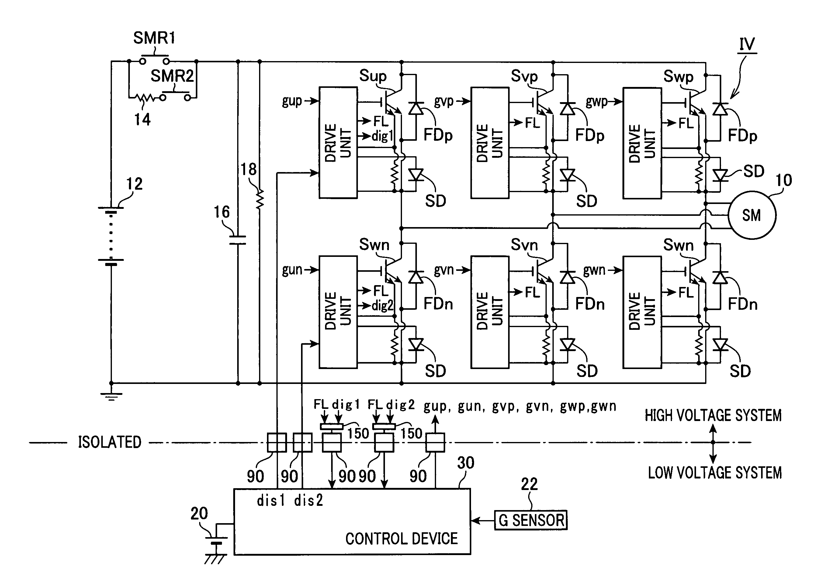
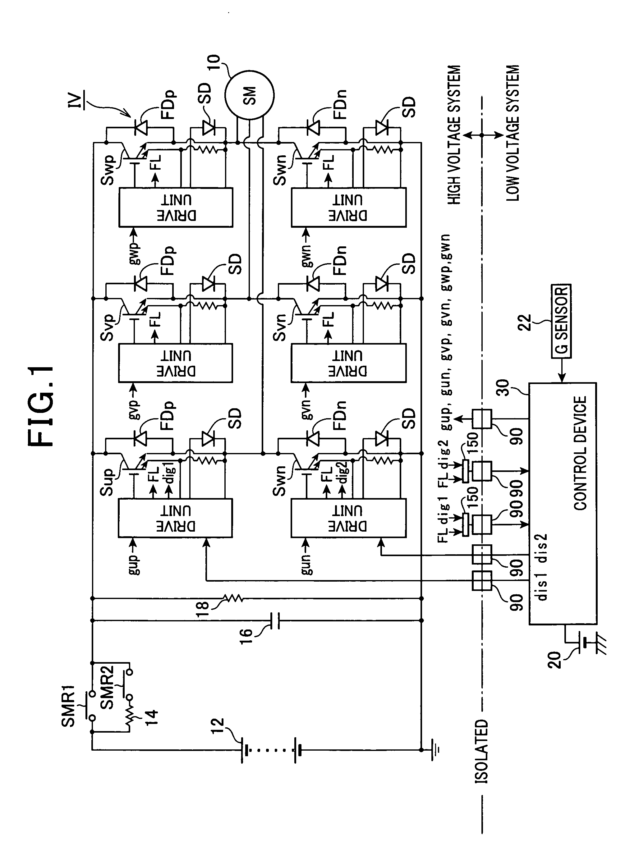
[0031]FIG. 1 is a system configuration according to a first embodiment of the present invention. A motor generator 10 as shown in FIG. 1 is a main equipment of the vehicle and is mechanically connected to a drive wheel (not shown). Further, the motor generator 10 is connected to a high voltage battery 12 via an inverter IV (power conversion circuit) and a parallel-connected circuit block having a relay SMR2 with a resistor 14 and a relay SMR1 which are connected in parallel. As to the high voltage battery 12, the terminal voltage exceeds e.g. more than 100 V. Also, a capacitor 16 and a discharge resistor 18 are disposed closer to the inverter IV side than the circuit block consisting of the relay SMR2 and SMR1. ...

second embodiment

[0071]With reference to FIG. 8, hereinafter will be described a second embodiment of the present invention. In the second embodiment, difference between the above-described first embodiment and the second embodiment is mainly described.

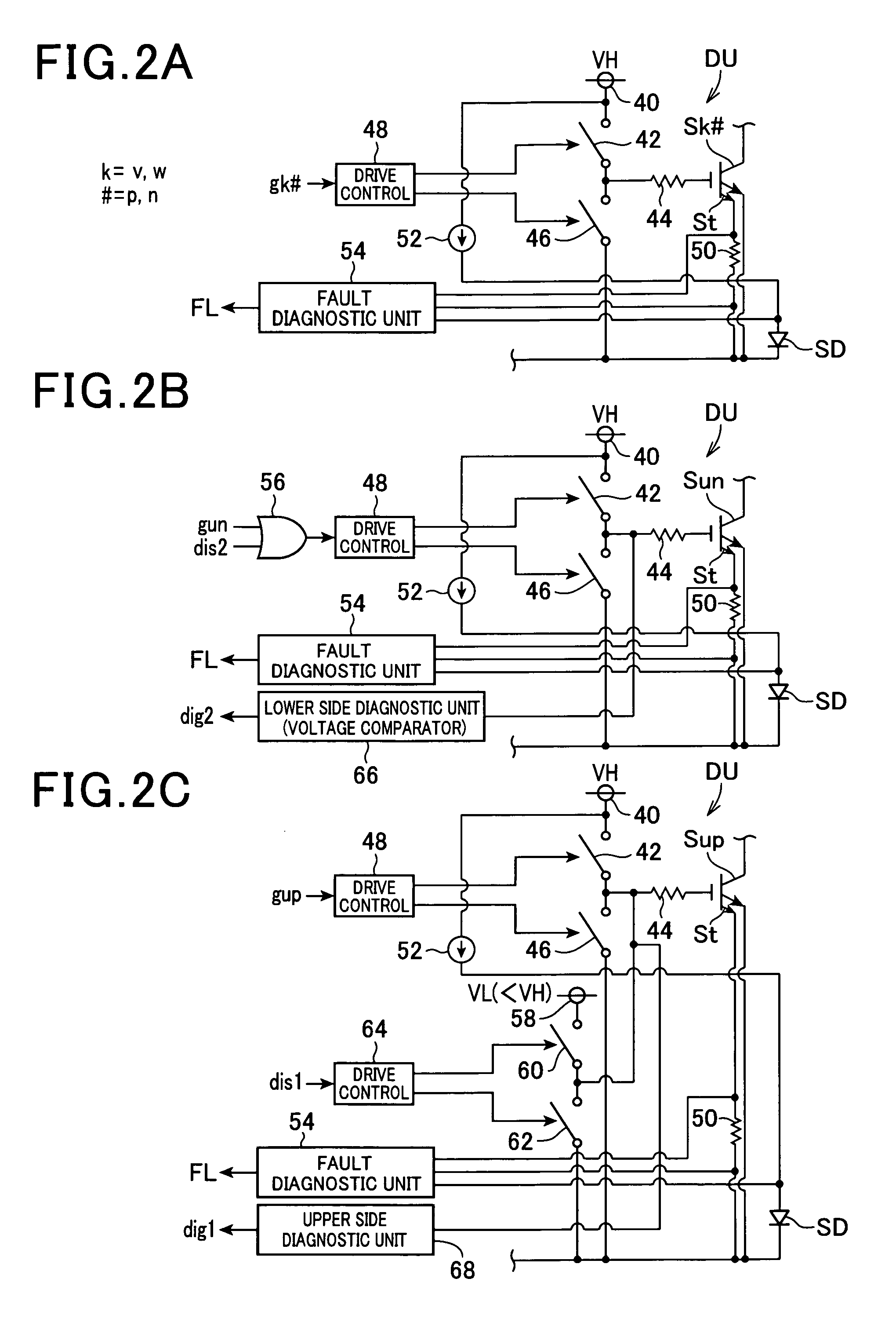
[0072]As shown in FIG. 8, a circuit configuration for transmitting signals including the failure signal FL outputted by the fault diagnostic unit 54, the diagnostic signal dig 2 outputted by the lower-side diagnostic unit 66 and the diagnostic signal dig1 outputted by the upper-side diagnostic unit 68, to the control device 30, is described. In FIG. 8, the same components as used in FIG. 7 or the components corresponding to those in FIG. 7 are applied with the same reference numbers.

[0073]According to the second embodiment, the photocoupler 90 is configured such that the photo diode included in the photocoupler 90 emits light when it is an abnormal situation where at least the failure signal FL or the diagnostic signals dig1 (dig2) is outputted by the...


PUM


Abstract

A discharge control apparatus arranged in a power conversion system having high-side switching element and low-side switching element to convert the DC power from the battery to a predetermined type of power. The discharge control is performed to discharge a capacitor connected in parallel to the switching elements when an abnormal event occurs. The discharge control apparatus is configured to simulate the operation of the switching elements assuming occurrence of the abnormal event, and transmits a plurality of signals representing the simulation result to a control device via a common photocoupler that isolates the switching elements side and the control device side. The control device diagnoses whether or not a fault occurs in the discharge control or the like by the simulation result.

Description

CROSS REFERENCE TO RELATED APPLICATION[0001]This application is based on and claims the benefit of priority from earlier Japanese Patent Application No. 2010-112010 filed on May 14, 2010 the description of which is incorporated herein by reference.TECHNICAL BACKGROUND[0002]1. Field of the Invention[0003]The present invention relates to power systems and, more particularly to a discharge control apparatus arranged in a power conversion system.[0004]2. Description of the Related Art[0005]Conventionally, various types of power systems have been provided. For instance, a Japanese Patent No. 3289567 discloses a power system including a motor connected to an inverter unit in which a capacitor is connected between a pair of input terminals. The power system further includes a control unit which is adapted to control a discharging of the capacitor. Particularly, the control unit controls switching elements of the inverter unit such that the torque of the motor becomes approximately zero and...

Claims


Application Information

Patent Timeline
IPC IPC(8): B60L3/00H02H9/00
CPCB60L3/0007B60L3/003B60L3/04B60L11/1803Y02T10/7066H02M1/32H03K17/0828H03K17/18Y02T10/7005B60L11/1868B60L50/51B60L58/20Y02T10/70
Inventor SHINDO, YUSUKEMAEBARA, TSUNEOMIURA, RYOTARO
Owner DENSO CORP
Why Eureka
Try Eureka