
Method for manufacturing display panel and display device substrate

a technology of display panel and substrate, which is applied in the manufacture of electrode systems, electric discharge tubes/lamps, discharge tubes luminescnet screens, etc., can solve the problems of vapor deposition problems, the throughput and yield of display devices deteriorate, and the deterioration of organic el elements during the formation of driving circuits, so as to prevent the deterioration of the driving circuit during the formation of organic el elements, the effect of simple steps

Inactive Publication Date: 2011-11-17
SUMITOMO CHEM CO LTD
View PDF2 Cites 19 Cited by
  • Summary
  • Abstract
  • Description
  • Claims
  • Application Information

AI Technical Summary

Benefits of technology

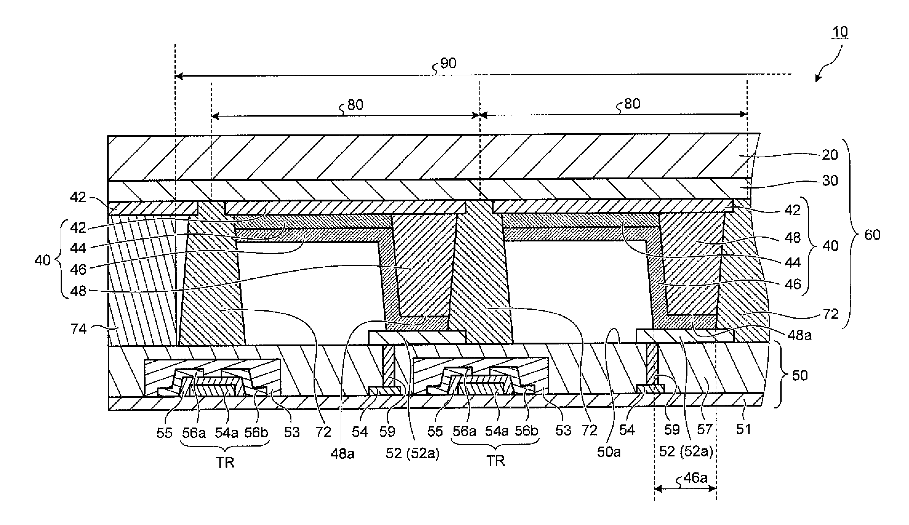
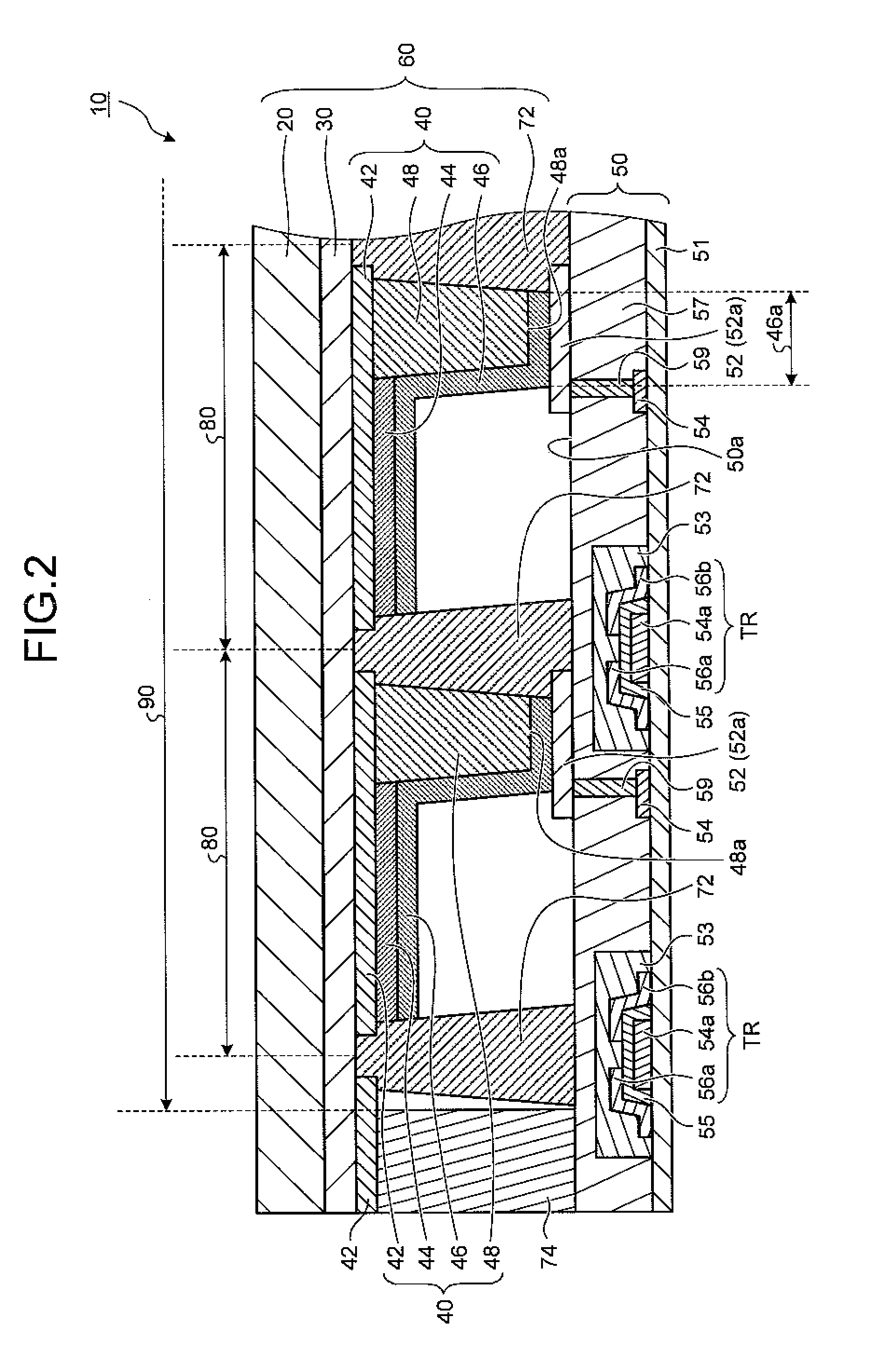
[0033]In the method for manufacturing a display device substrate according to the present invention, a display device substrate formed by providing on a first substrate, which is equipped with a plurality of filter elements, a plurality of organic EL elements having the same structure as each other, and a driving substrate formed with a driving circuit are separately prepared. Then, the display device substrate and the driving substrate are laminated. Consequently, deterioration of the organic EL elements during formation of the driving circuit can be prevented, and deterioration of the driving circuit during formation of the organic EL elements can be prevented. As a result, a display panel having a driving circuit for individually driving a plurality of organic electroluminescent elements can be manufactured by simple steps at a good yield.
[0034]Further, since a plurality of organic EL elements having the same structure as each other are formed on a color filter, when forming the light-emitting layer of the organic EL elements, it is not necessary to manufacture a plurality of kinds (for example, three kinds) of light-emitting layer. Therefore, when forming the light-emitting layer by vapor deposition, the light-emitting layer for all of the organic EL elements can be formed in one vapor deposition step. Further, when forming the light-emitting layer by a coating method, there is no need for a high-precision technique for separately coating the light-emitting materials, so that the light-emitting layer can be formed in one coating step by a simple method such as a spin coating method or a capillary coating method.
[0035]Thus, because the manufacturing steps can be simplified, an increase in the number of steps can be suppressed, and stable manufacturing can be achieved, throughput and yield can be improved. Consequently, the failure rate of the manufactured display device substrates and of a display device substrate embedded in display panels can be reduced.
[0036]In the method for manufacturing a display panel according to the present invention, even if a failure in the display device substrate is discovered after the driving substrate and the display device substrate have been laminated, since the organic EL elements are not formed on the driving substrate, the expensive driving substrate can be easily removed and reused (reworked). Accordingly, additional cost reductions can be achieved.
[0037]In addition, in the method for manufacturing a display panel according to the present invention, since the organic EL elements are provided without providing a space between the organic EL elements and the color filter, water vapor, oxygen and the like can be prevented from coming into contact with the organic EL elements. Consequently, an extension of life time for the organic EL elements can be achieved.
[0038]In the display panel according to the present invention, the organic EL elements are provided on a color filter. Even if there was a predetermined gap defined between the organic EL elements and the color filter, when the display screen is viewed from a direction perpendicular to the screen (hereinafter, “screen perpendicular direction”), since each of the organic EL elements is overlapped with each of the filter elements when viewing in the screen perpendicular direction, the light emitted from each organic EL element is perceived as passing through the filter element arranged at an overlapping position as viewed from the screen perpendicular direction. For that reason, the problem of color mixing does not occur. However, when the display screen is viewed from an oblique direction to the screen, the light emitted from each organic EL element may be perceived as passing through the filter element arranged adjacent to the filter element arranged at the overlapping position as viewed from the screen perpendicular direction. Consequently, although the problem of color mixing arises depending on the angle that the display screen is viewed at, in the present invention, since the organic EL elements are provided on the color filter, the gap defined between the organic EL elements and the color filter can be narrowed. Further, since in some cases the organic EL elements can also be arranged in contact with the color filter, the perception that the light emitted from each organic EL element is passing through the filter element arranged adjacent to the filter element arranged at the overlapping position as viewed from the screen perpendicular direction can be prevented. Consequently, the problem of color mixing can be suppressed.

Problems solved by technology

However, the more kinds of organic EL element that have to be formed, the greater the number of manufacturing steps, and the more difficult the manufacturing steps themselves become.
As a result, there is the problem that display device throughput and yield deteriorate.
When forming the light-emitting layer by a coating method, since the coating solutions need to be separately coated on respective predetermined regions, the same problems as for vapor deposition occur.

Method used


Image

  • Method for manufacturing display panel and display device substrate
  • Method for manufacturing display panel and display device substrate
  • Method for manufacturing display panel and display device substrate

Examples


Embodiment Construction

[0043]Embodiments of the present invention will now be described with reference to the drawings. To allow the invention to be easily understood, the shape, size, and arrangement of the constituent elements are merely schematically illustrated. The present invention is not limited to the following description. Further, the respective constituent elements may be appropriately changed within the scope of the invention. In the figures used in the following description, constituent elements that are the same are denoted with the same reference numerals, and repetitive descriptions in separate embodiments may be omitted. In addition, although there are parts such as electrode leads in the device in which the organic EL elements are mounted, a description of such parts may be omitted since they have no direct bearing on the description of the present invention. The device according to the present invention in which organic EL elements are mounted is not necessarily manufactured or used wit...


PUM


Abstract

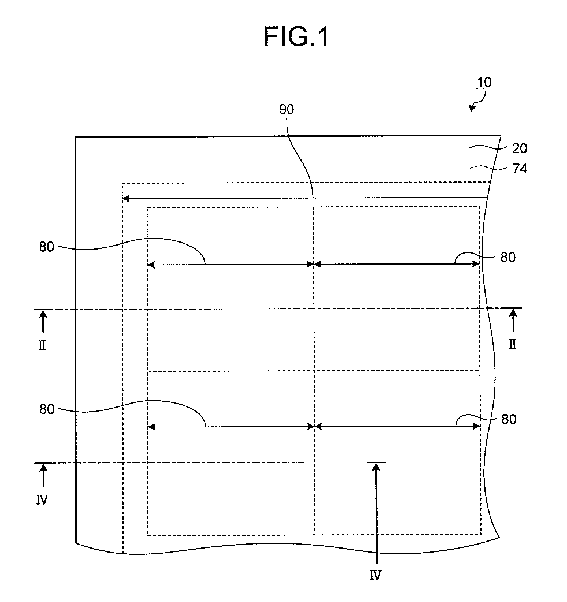
A method for manufacturing a display panel comprises the steps of: forming a display device substrate 60 by providing on a first substrate 20, which is equipped with a color filter 30 on which a plurality of filter elements are arranged, a plurality of organic electroluminescent elements 40, which have the same structure as each other and which is individually equipped with a connection electrode formed with a connection terminal 46a, so that each of organic electroluminescent elements is overlapped with each of the filter elements; preparing a driving substrate 50, which comprises a driving circuit for driving the plurality of and a connection portion 52a that establishes electrical connection to the driving circuit; arranging a laminating material 74X on a surface of the display device substrate or the driving substrate so as to enclose the plurality of organic electroluminescent elements when the display device substrate and the driving substrate are laminated; and laminating the display device substrate and the driving substrate so that the connection terminal and the connection portion come into contact each other.

Description

TECHNICAL FIELD[0001]The present invention relates to a method for manufacturing a display panel comprising a plurality of organic electroluminescent elements (hereinafter, referred to as “organic EL element”), a display device substrate used in this manufacturing method, a display panel comprising this display device substrate, and a display device comprising this display panel.BACKGROUND ART[0002]The development of flat panel displays (hereinafter, referred to as “organic EL display device” or simply “display device”) that use self-emitting type organic EL elements as a pixel light source is progressing. In organic EL display devices mounted is a display panel that outputs three kinds of light, red, green, and blue, enabling a color display to be achieved by superimposing the three kinds of light at a predetermined light intensity ratio.[0003]A display panel for color display can be realized by providing three kinds of organic EL element, which respectively emit red, green, and bl...

Claims


Application Information

Patent Timeline
Patent Type & Authority Applications(United States)
IPC IPC(8): H05B33/02H05B33/10
CPCH01L27/3253H01L27/322H10K59/38H10K59/1275H05B33/02H05B33/04H10K71/00
Inventor NISHIOKA, YUKIYAKURIHARA, TAKASHIKAJITANI, MASARU
Owner SUMITOMO CHEM CO LTD
Learn More