Method of measuring terahertz wave and apparatus therefor

a terahertz wave and measurement method technology, applied in the field of apparatus and measuring terahertz waves, can solve the problems of difficult real-time acquisition of such pulses, low signal of terahertz wave output from the sensor unit, and limited output of the circuit, so as to improve the signal-to-noise ratio of the measured wave

Inactive Publication Date: 2011-11-24
CANON KK
View PDF2 Cites 6 Cited by
  • Summary
  • Abstract
  • Description
  • Claims
  • Application Information

AI Technical Summary

Benefits of technology

[0009]In the method according to the aspect of the present invention, the offset current having no relation to a change in the electric field of a terahertz wave that reaches the sensor unit is determined in the waiting state. In the measurement, the offset current is subtracted from the current signal input to the current detection unit to detect only the signal component originating from the change in the electric field of the terahertz wave. This makes it possible to improve the signal-to-noise ratio of the measured wave.

Problems solved by technology

Due to the slow response that current electronics have with respect to the speed of THz waves, it is generally difficult to acquire such a pulse in real time.
Another obstacle in detecting a terahertz wave is that a signal of a terahertz wave output from the sensor unit is extremely low in strength.
However, a rated output is defined for the circuit depending on its circuit configuration, and the output of the circuit is limited by the rating.

Method used


Image

  • Method of measuring terahertz wave and apparatus therefor
  • Method of measuring terahertz wave and apparatus therefor
  • Method of measuring terahertz wave and apparatus therefor

Examples


first embodiment

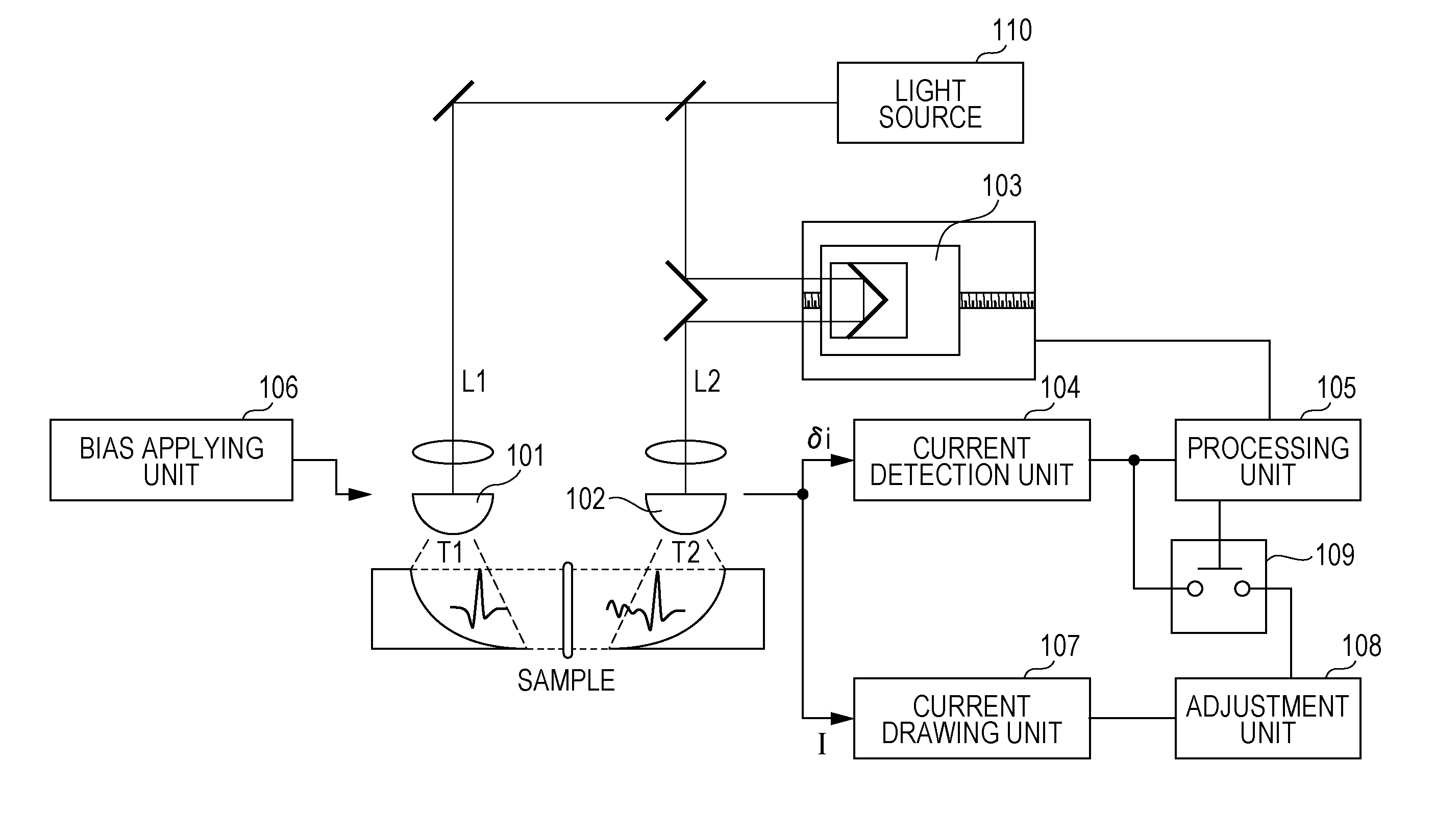
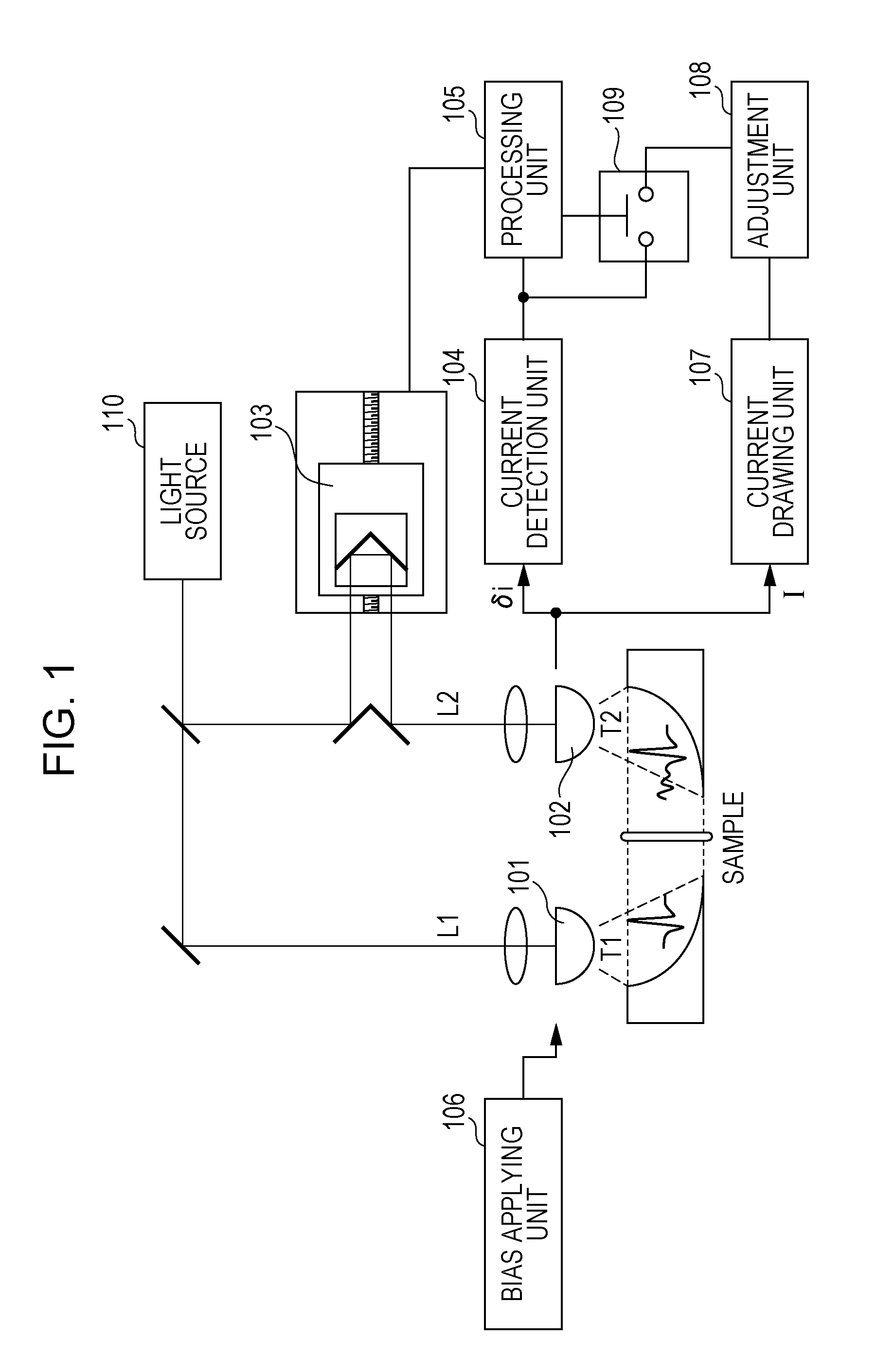
[0049]A first embodiment is described. In the following description, similar parts to those described above are not explained again to avoid unnecessary repetition. The measurement technique according to the present embodiment is applicable to both the step-and-scan method and the rapid scan method. In the present embodiment, the waiting state is provided in a preparation period before the measurement is started. More specifically, the waiting state refers to a state immediately before the measurement of the terahertz wave is started. In the waiting state, the measuring apparatus waits for a measurement start trigger to be issued. In the present embodiment, in this waiting state, the optical delay unit 103 adjusts the length of the optical path of excitation light such that the excitation light traveling on the optical path L2 arrives at the sensor unit 102 before the terahertz wave pulse arrives at the sensor unit 102. That is, in the waiting state, a baseline correction of the mea...

second embodiment

[0053]A second embodiment is based on the first embodiment described above, but the operation flow according to the first embodiment is modified such that the operation flow includes an additional step of cutting off the terahertz wave in the waiting state. A description of similar processing steps to those described above is omitted in the following explanation. In the present embodiment, the waiting state is intentionally provided such that it is inserted in an operation of measuring the time-domain waveform. When the waiting state is intentionally inserted, the terahertz wave applied to the sensor unit 102 is cut off, and the measurement correction is performed in this state in which no terahertz wave reaches the sensor unit 102. Note that the method of cutting off the terahertz wave such that it does not reach the sensor unit 102 during the waiting state may be employed in other embodiments as well.

[0054]FIG. 5A is a flow chart illustrating a measurement process according to the...

third embodiment

[0058]A third embodiment disclosed below is also based on the first embodiment, but the operation flow according to the first embodiment is modified such that the waiting state is provided in a different manner. A description of similar processing steps to those described above is omitted in the following explanation. In the present embodiment, the waiting state is provided in a preparation period before the measurement is started. More specifically, the waiting state is provided in a period from a time at which measurement of a first time-domain waveform by the optical delay unit 103 is ended to a time at which measurement of a second time-domain waveform is started. In the present embodiment, the correction of the measuring apparatus is performed based on the signal output from the current detection unit 104 during this period.

[0059]FIG. 6A is a flow chart illustrating a measurement process according to the third embodiment. FIG. 6B is a diagram illustrating a concept of an operat...


PUM

PropertyMeasurementUnit
terahertz-wave current δiaaaaaaaaaa
widthaaaaaaaaaa
lengthaaaaaaaaaa

Abstract

In a measurement of a time-domain waveform of a terahertz wave based on time-domain spectroscopy, a current signal including a component originating from the terahertz wave is detected using a photoconductive device, and a voltage signal corresponding to the detected current signal is detected. At a pre-processing stage before the voltage signal detection, an offset current included in the detected current signal and having no relation to the terahertz wave is drawn. The offset current is monitored and the magnitude of the drawn offset current is adjusted according to a result of the monitoring. A time-domain waveform of the terahertz wave is acquired based on the voltage signal detected while drawing the offset current. The monitoring of the offset current and the adjusting of the offset current are performed in a waiting state in which measurement of the time-domain waveform of the terahertz wave is not performed.

Description

BACKGROUND OF THE INVENTION[0001]1. Field of the Invention[0002]The present invention relates to an apparatus and a method of measuring a terahertz wave, and particularly, to an apparatus and a method of measuring a terahertz wave in time domain. Hereinafter, such as an apparatus will be also referred to as a THz TDS (Time Domain Spectroscopy) apparatus. More particularly, the present invention relates to a technique to suppress an offset current in a measuring apparatus.[0003]2. Description of the Related Art[0004]A terahertz (THz) wave is an electromagnetic wave with a frequency in an arbitrary frequency band within a range from 0.03 THz to 30 THz. This frequency range includes frequencies or bands of frequency at which characteristic absorption occurs due to structures or states of substances such as biological molecules. This characteristic absorption feature is useful to nondestructively analyze or identify a substance. Active efforts are currently being made to develop testing...

Claims


Application Information

Patent Timeline
Patent Type & Authority Applications(United States)
IPC IPC(8): G01R31/00G01N21/35G01N21/3586
CPCG01R13/347
Inventor ITSUJI, TAKEAKI
Owner CANON KK
Why Eureka
Try Eureka