Eureka AIR delivers breakthrough ideas for toughest innovation challenges, trusted by R&D personnel around the world.

Device for discriminating the phase and the phase variation of a signal

a technology of phase variation and signal, applied in oscillation comparator circuits, automatic control of pulses, instruments, etc., can solve the problems of divergence of loops and dropouts, significant doppler frequency variation in signals received by receivers, and overhead in terms of computational load for receivers

Active Publication Date: 2011-11-24
THALES SA
View PDF0 Cites 3 Cited by
  • Summary
  • Abstract
  • Description
  • Claims
  • Application Information

AI Technical Summary

Benefits of technology

The invention is a device that improves the resilience of a system to phase dynamics without increasing the operating point in terms of signal-to-noise ratio. It uses a frequency-extended winder discriminator to estimate the phase error of a complex signal. The device also includes means for coherent integration of the signal and a phase-locked loop to lock the phase of a local carrier onto the received carrier. The technical effects of the invention include increased resilience to phase dynamics, reduced computational load, and improved signal-to-noise ratio.

Problems solved by technology

In the case where the carrier is an aircraft, the accelerations of motion that it is liable to cause result in a significant Doppler frequency variation in the signals received by the receiver.
Moreover, it requires an increase in the passband of the loop, thus giving rise to an overhead in terms of computational load for the receiver.
In the case of slackness of the said loop, also called the carrier loop, during the transient phase between the two stationary states, the phase error may depart from the discriminator capture zone and this may give rise to the divergence of the loop and its dropout.
It remains, however, limited in terms of frequency error or phase velocity error.
This limitation is directly related to the sampling frequency used by the digital device which executes the loop.
In a satellite radionavigation receiver, the limitation of the phase loop sampling frequency is related to the duration of coherent integration applied to demodulate the received signal.
Another known solution consists in making direct use of a frequency-locked loop but in this case, the phase measurement is much less accurate, this being penalizing to performance in terms of accuracy and integrity of the positioning measurement.

Method used


Image

  • Device for discriminating the phase and the phase variation of a signal
  • Device for discriminating the phase and the phase variation of a signal
  • Device for discriminating the phase and the phase variation of a signal

Examples


Embodiment Construction

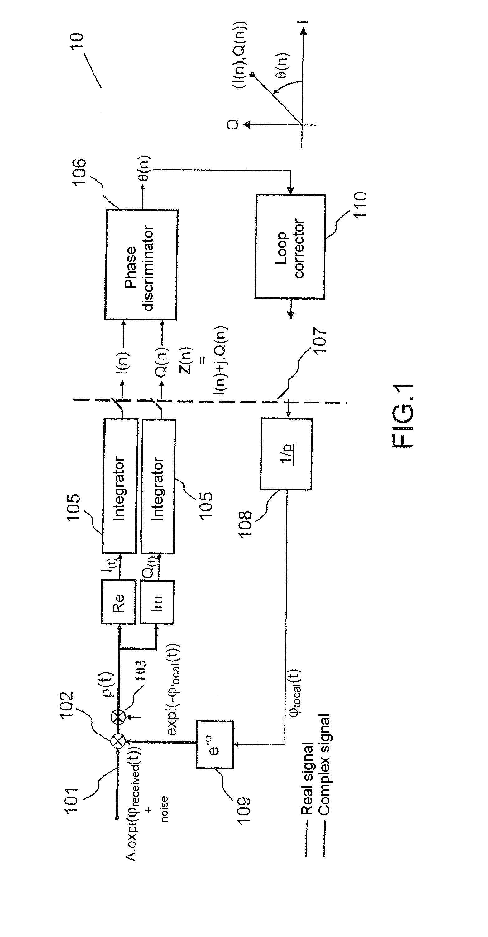
[0038]FIG. 1 shows diagrammatically the principle of the demodulation of the signal received by a satellite radionavigation receiver 10. The processing actions situated to the left of the dashed line constitute a continuous or discrete system with a high sampling frequency Fc, for example equal to 100 MHz. They are carried out preferably by integrated circuits of ASIC or FPGA type which are compatible with a high frequency such as this. The processing actions situated to the right of the dashed line constitute a system sampled at a low frequency, for example equal to 50 Hz, and are carried out by software, for example DSP signal processing software.

[0039]The received signal 101 is demodulated by a local carrier 109 of phase φlocal(t) by way of a complex multiplier 102. The term “local carrier” designates a signal generated locally at a second frequency different from that of the received signal, this second frequency being controlled by virtue of a digitally-controlled oscillator 10...


PUM


Abstract

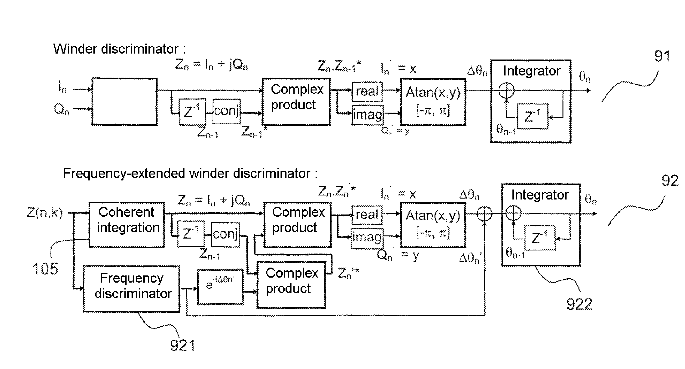
In a phase discriminator device for receiving, as input, a complex signal whose argument represents a phase error, and for producing, as output, an estimate of the phase error for each signal sample Zn+1 received, the device includes a frequency discriminator and a computation part for determining the phase estimate obtained at an instant (N+1)T1. The computation part determines the phase estimate according to predetermined relations, and T1 is the time interval between two samples Zn and Zn+1, received consecutively.

Description

CROSS-REFERENCE TO RELATED APPLICATIONS[0001]This application claims priority to foreign French patent application No. FR 10 02152, filed on May 21, 2010, the disclosure of which is incorporated by reference in its entirety.FIELD OF THE INVENTION[0002]The technical field of the invention is that of devices for demodulating a signal in a reception system for which an accurate estimation of the phase is required. The invention applies, for example, to satellite radionavigation systems for which the information contained in the phase of the signal helps in accurately determining the position of a receiver.[0003]The invention relates to a device for discriminating or estimating the phase or phase error during the demodulation of a signal subject to significant phase variations, for example due to a rapid trend in the frequency due to the Doppler effect. In the subsequent description the use of the term Doppler frequency is made with reference to a frequency bias due to the velocity of t...

Claims


Application Information

Patent Timeline
Patent Type & Authority Applications(United States)
IPC IPC(8): G01S19/29H03D13/00
CPCH03L7/085G01S19/29
Inventor MARTIN, NICOLASPERRE, JEAN-MICHEL
Owner THALES SA
Why Eureka
Eureka Blog
Learn More