Modular plant for removal of pollutants from flue gases produced bv industrial processes

Inactive Publication Date: 2011-11-24
AST ENG +1
View PDF6 Cites 27 Cited by
  • Summary
  • Abstract
  • Description
  • Claims
  • Application Information

AI Technical Summary

Benefits of technology

[0008]A plant for the removal of pollutants from flue gases produced by industrial processes that overcomes the drawbacks mentioned above has now been made and is the object of the present invention. Said plant for the removal of pollutants is easy to be

Problems solved by technology

These are not modular, may be large sized, with consequent difficulties for assembly, transport, on site assembly and their need for repair and routing maintenance imply expensive and unavoidable stoppage of the production plants.
Moreover, there are no efficient plants that beside

Method used


Image

  • Modular plant for removal of pollutants from flue gases produced bv industrial processes
  • Modular plant for removal of pollutants from flue gases produced bv industrial processes
  • Modular plant for removal of pollutants from flue gases produced bv industrial processes

Examples


case i

[0297] Separation Unit with Ceramic Membranes and Flow Type “Complete Mixing”.

[0298]Let's consider a separation unit consisting of a ceramic membrane APS / MS / Al2O3S shown in Table 5. Two values of pressure ratio have been considered, 20 and 30 (the gas to be treated is at atmospheric pressure).

[0299]The main results are summarised in the following Table 6:

TABLE 6Complete mixing.pI / pIIS(m2)yP (%)XL (%)Stage cut (%)20159297.28.7510.393077598.08.6010.40

[0300]It may be seen that while the degree of separation of carbon dioxide is considerable (above 97%), the required membrane surface is very high.

[0301]The rate of permeated gas rich in CO2 is equal to about 10% compared to the rate to be treated. In relation to the required purity level, of course it is possible to recirculate the rate in output from the separation unit mixing it to the gas to be treated, or treat it again in a subsequent unit.

[0302]It is possible to appreciate the considerable increase of the membrane surface as the re...

case ii

[0306] Separation Unit with Ceramic Membranes and Flow Type “Equicurrent”.

[0307]Let's consider two separation units consisting of two different membranes, APS / MS / Al2O3S and APS / MS / Al2O3H, having selectivity CO2 / N2 respectively 800 and 50 (Table 7). Two pressure ratio value have been considered, 20 and 30.

[0308]Table 7 shows the main results relating to membrane APS / MS / Al2O3S having selectivity equal to 800. It is seen, for example, that quite similar performance compared to the case of complete mixing flow can be achieved with a membrane surface equal to 400 m2.

TABLE 7Flow in equicurrent and ceramic membranes.pI / pIIS(m2)yP (%)XL (%)Stage cut (%)2040098.68.810.153040098.45.413.47

[0309]The calculations were repeated for membrane APS / MS / Al2O3H and the performance of the two ceramic membranes was compared, the membrane surface being equal (400 m2).

[0310]Membrane APS / MS / Al2O3H shows it achieves a purity degree (yp) clearly higher but a similar stage cut.

case iii

[0311] Separation Unit with Polymeric Membranes and Flow Type “Equicurrent”.

[0312]A separation unit was considered, consisting of polymeric membranes the data of which are shown in Table 8 (Baker, 2004).

TABLE 8Permeability in barrer (10−10 cm3(STP) cm / cm2sPa) of somepolymers.RubbersGlassesSiliconePolyimiderubberNatural rubberCellulose acetatePolysulfone(Ube Industries)at 25° C.at 30° C.at 25° C.at 35° C.at 60° C.Gas(Tg - 129° C.)(Tg - 73° C.)(Tg 40-124° C.)(Tg 186° C.)(Tg > 250° C.)H255041241450Hc30031331340O2500231.61.43N22509.40.330.250.6CO22700153105.61.3CH4800300.360.250.4C2H62100—0.20—0.08C3H834001680.13—0.015C4H107500—0.10——

[0313]The performance of a cellulose acetate membrane was compared with a polyamide one. While the purity degree obtained is lower than that obtained with the ceramic membranes, it is possible to see that the membrane surface in both cases is greatly reduced (from 400 m2 to 50 m2).

[0314]An analysis of the available membranes, especially at a commercial leve...


PUM

PropertyMeasurementUnit
Temperatureaaaaaaaaaa
Pressureaaaaaaaaaa

Abstract

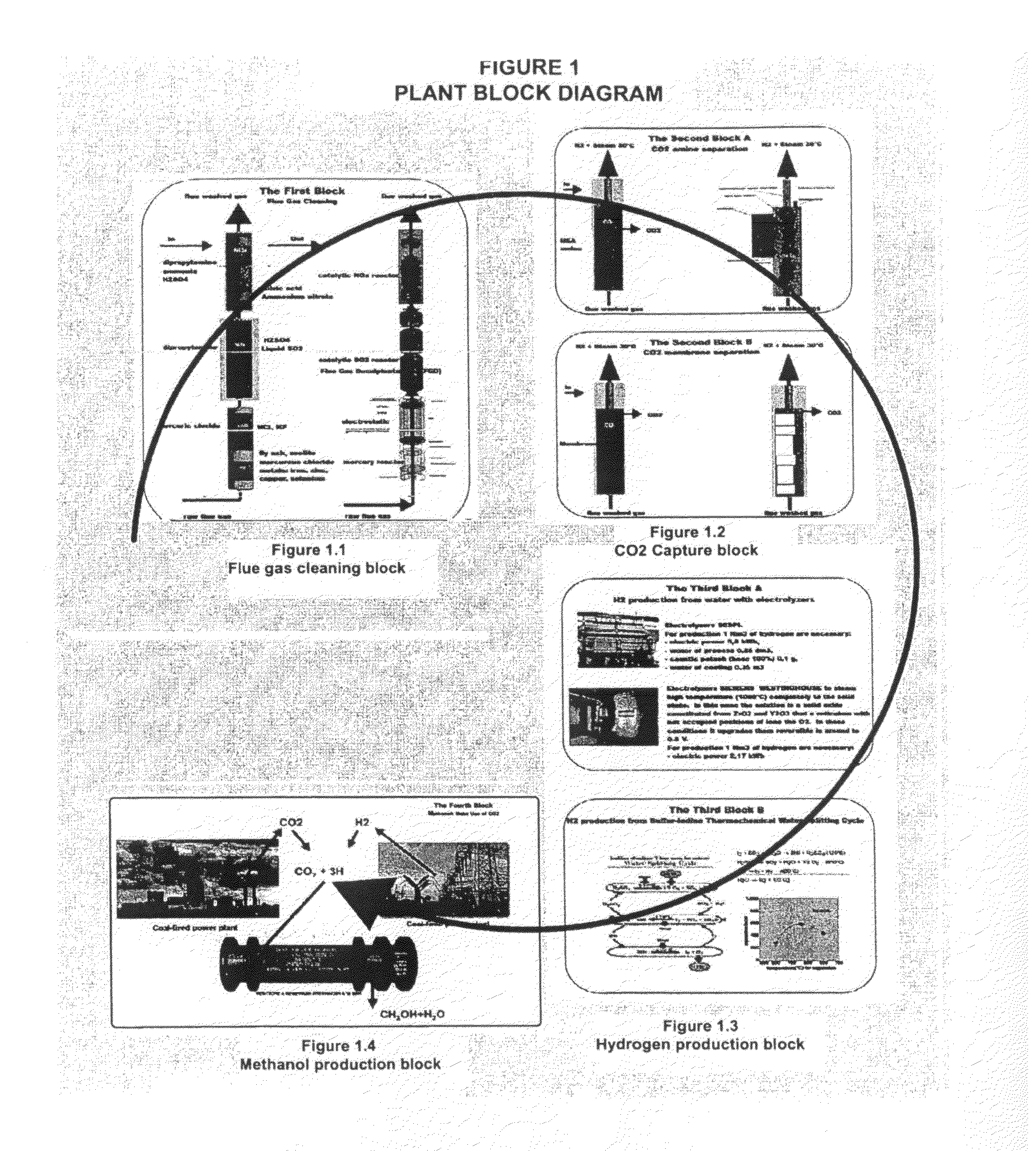
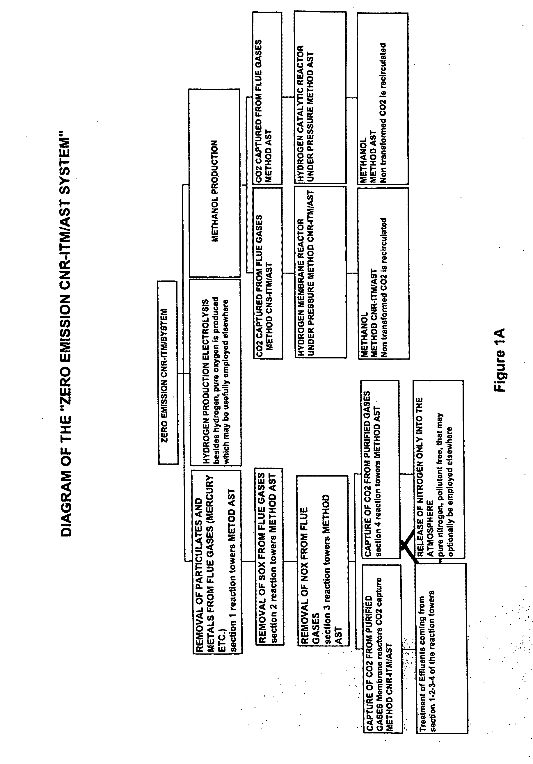
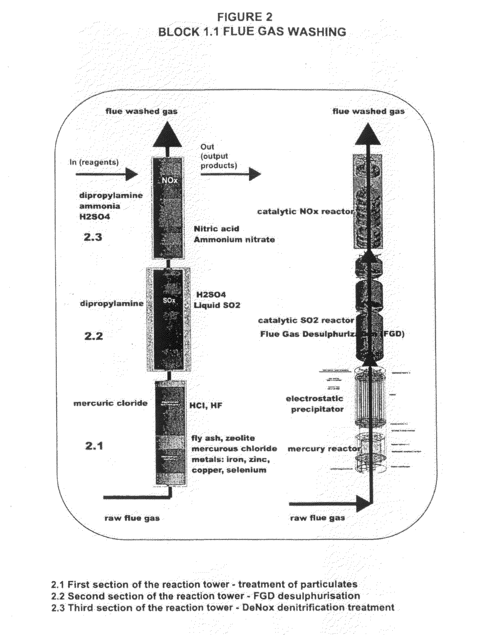
The invention relates to a so-called zero emission ‘AST-CNR/ITM system’ modular plant for removal of pollutants from flue gases produced by industrial processes. The plant comprises prefabricated modular elements with programmed and automatic operation, easy to mount and assemble on site without undergoing expensive plant stoppage. Each module or ‘reaction tower’ comprises a plurality of sections vertically arranged on top of one another, which carry out the following functions: Removal of particulate matter with treatment and removal of chemical pollutants, such as heavy metals, chlorides, fluorides Treatment and removal of SOx Treatment and removal of NOx Capture of CO2 Production of hydrogen Production of methanol The various sections may be combined according to the requirements of the plant and of the flue gases to be treated.

Description

FIELD OF THE INVENTION [0001]The present invention relates to a modular plant for removal of pollutants from flue gases produced by industrial processes.[0002]In particular, the invention relates to a plant, constituting the so-called zero emission “AST-CNR / ITM system”, the plant being equipped for smoke treatment, for separating and using the pollutants removed, for capturing CO2 and transforming it into methanol in the membrane reactors comprised in the plant. This is composed of prefabricated modular elements with programmed and automatic operation, easy to mount and assemble on site without undergoing expensive plant stoppage.PRIOR ART [0003]It is known that industrial plants generate polluting substances that are subject to strict rules in relation to their release to the environment. To this end, industrial plants are provided with special devices / plants for the disposal / treatment thereof.[0004]In the present description, reference is made to industrial flue gases from industr...

Claims


Application Information

Patent Timeline
IPC IPC(8): C07C27/00B01D53/86B01D53/62B01D53/50B01D53/56B01D53/75B01D53/64
CPCB01D53/229B01D53/75Y02E60/36B01D53/77B01D53/86B01D2251/404B01D2256/16B01D2257/2045B01D2257/2047B01D2257/302B01D2257/404B01D2257/504B01D2257/602B01D2257/7027B01J2219/0002B03C3/017C01B3/068C01B2203/0485C07C29/152E04H5/02Y02C10/04Y02C10/06Y02C10/10C07C31/04Y02P20/151Y02P20/50Y02P20/582Y02P30/00Y02C20/40
Inventor NARDO, TOMMASONARDO, ANTONIO MARIABASILE, ANGELOGALLUCCI, FAUSTO
Owner AST ENG
Why Eureka
Try Eureka