
Combined cycle power plant with flue gas recirculation

a combined cycle power plant and flue gas recirculation technology, which is applied in the field of power plants, can solve the problems of more expensive and energy-consuming per kg of captured co2 than the systems of other types of fossil power plants, and the co2 concentration can be detrimental to the performance, efficiency and operation of the co2 capture system

Active Publication Date: 2011-12-01
ANSALDO ENERGIA SWITZERLAND AG
View PDF12 Cites 65 Cited by
  • Summary
  • Abstract
  • Description
  • Claims
  • Application Information

AI Technical Summary

Problems solved by technology

Due to the relatively low CO2 concentration of the flue gases of a conventional CCPP, such as 4% for example, the CO2 capture system (also called CO2 capture plant or CO2 capture equipment) for a conventional CCPP can be more costly and energy consuming per kg of captured CO2 than the ones for other types of fossil power plants, such as coal fired plants, which have a relatively higher CO2 concentration.
This variation in the CO2 concentration can be detrimental to the performance, efficiency, and operatability of the CO2 capture system.
However, flue gas recirculation reduces the oxygen content in the inlet gases of the gas turbine and affects combustion.
Besides positive effects on NOx emission the reduced oxygen content can lead to an incomplete unstable combustion and result in high CO emissions, which is highly undesirable.

Method used


Image

  • Combined cycle power plant with flue gas recirculation
  • Combined cycle power plant with flue gas recirculation
  • Combined cycle power plant with flue gas recirculation

Examples


Embodiment Construction

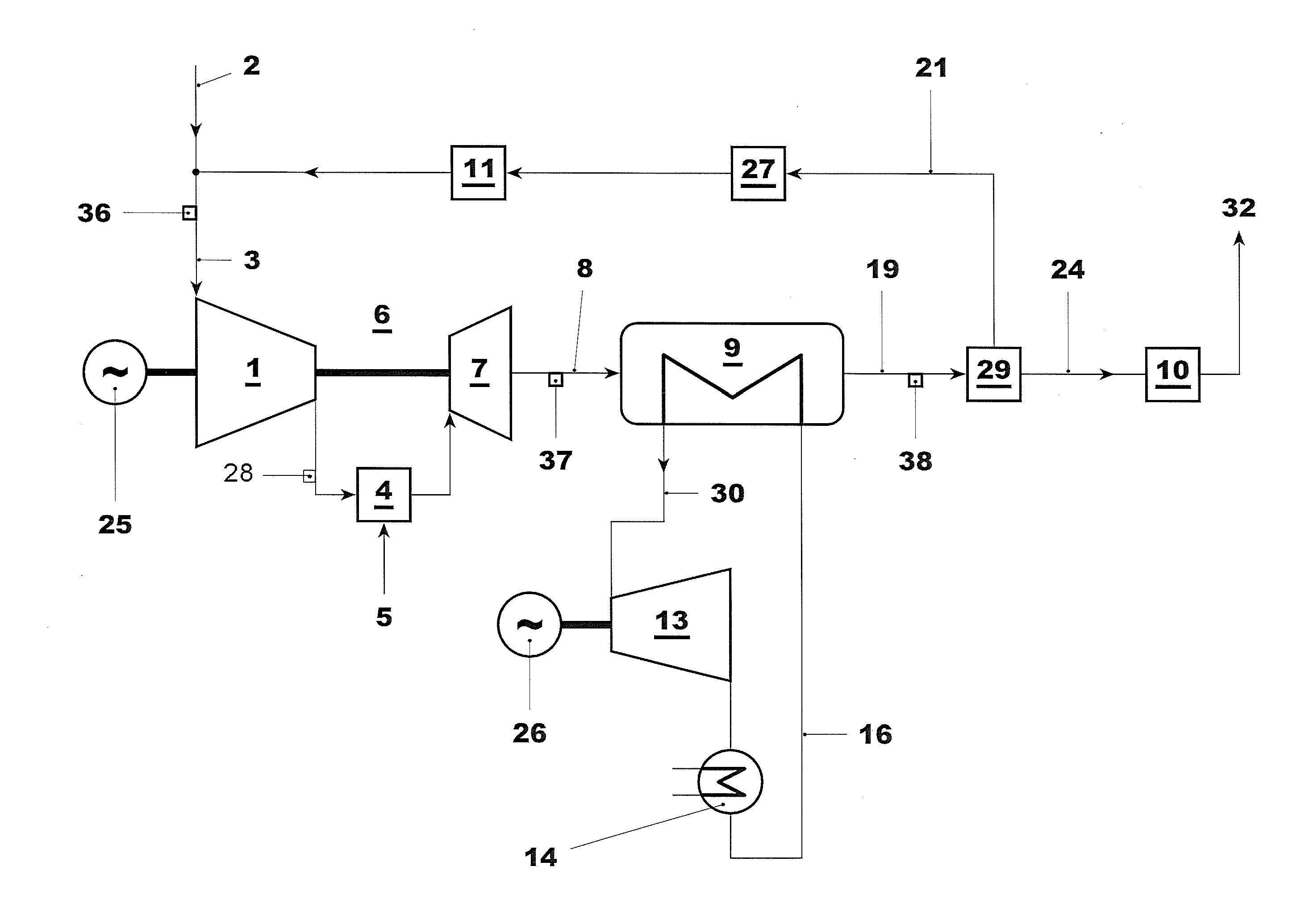
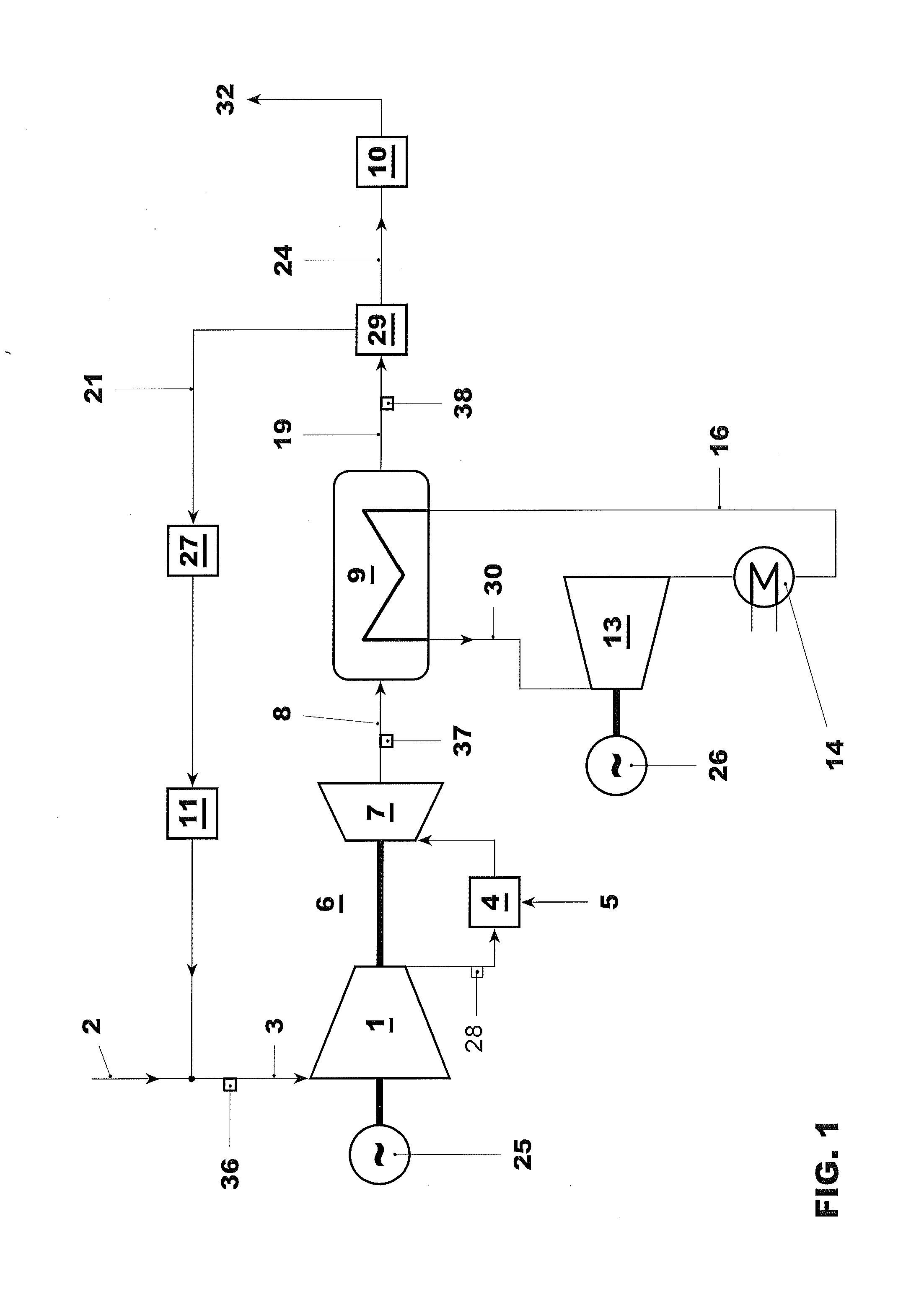
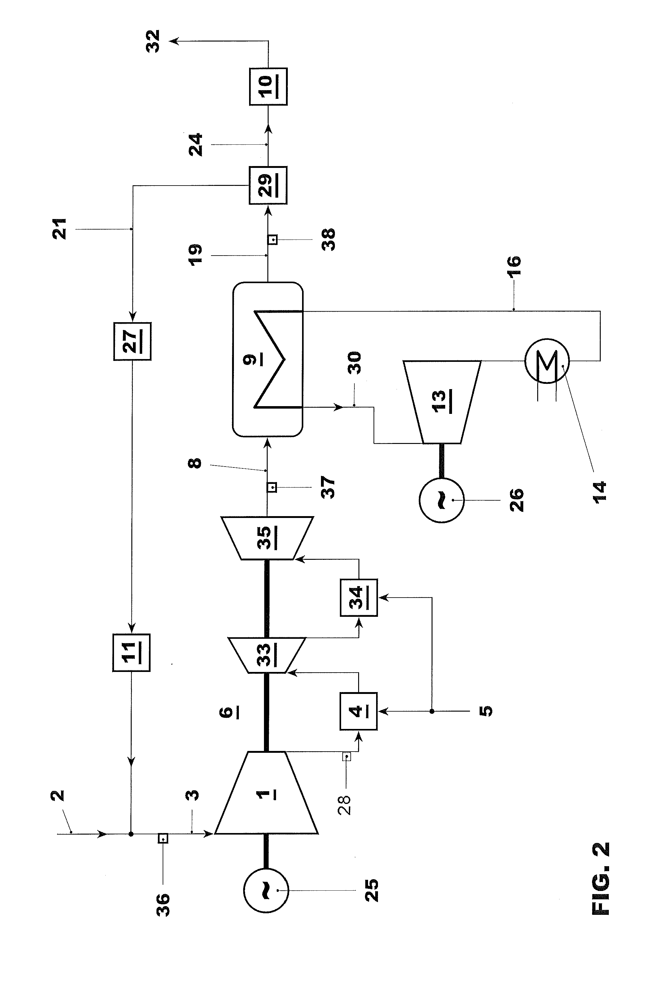
Exemplary embodiments of the present disclosure provide a low CO emission and low NOx emission operating method for a combined cycle power plant (CCPP) that includes at least one gas turbine with flue gas recirculation, one heat recovery steam generator (HRSG), and one steam turbine, as well as a plant designed to operate according to an exemplary method.

The exemplary embodiments also allow a high flue gas recirculation rate while maintaining stable, clean combustion and to provide a flexible operation method for flue gas recirculation operation.

Exemplary embodiments of the present disclosure take advantage of the finding that burn out of CO, in other word reaction of CO with oxygen to form CO2, is facilitated by a high combustion pressure. To take advantage of this effect an exemplary operating method, in which the flue gas recirculation rate is a function of the combustion pressure, is disclosed. The flue gas recirculation rate rFRG can be defined as the ratio of flue gas mass flo...


PUM


Abstract

An exemplary system method for the operation of a CCP P with flue gas recirculation to reduce NOx emissions and / or to increase the CO2 concentration in the flue gases to facilitate CO2 capture from the flue gases is disclosed. The flue gas recirculation rate (rFRG) is controlled as function of the combustion pressure and / or the hot gas temperature. Operability is enhanced by admixing of oxygen or oxygen enriched air to the gas turbine inlet gases or to the combustion.

Description

RELATED APPLICATIONThis application claims priority under 35 U.S.C. §119 to Swiss Patent Application No. 00841 / 10 filed in Switzerland on May 26, 2010, the entire content of which is hereby incorporated by reference in its entirety.FIELDThe disclosure relates to power plants, such as a method for operating a combined cycle power plant with flue gas recirculation as well as to a plant to carry out such a method.BACKGROUND INFORMATIONIn recent years it has become obvious that the generation of greenhouse gases leads to global warming and that further increase in greenhouse gas production will accelerate global warming. CO2 (carbon dioxide) is identified as a main greenhouse gas and NOx is believed to significantly contribute to the greenhouse effect as an indirect greenhouse gas by producing ozone in the troposphere. CCS (carbon capture and storage) and reduction of NOx emissions are considered potential major means to reduce and to control global warming.Reduction of NOx emissions ca...

Claims


Application Information

Patent Timeline
IPC IPC(8): F02M25/07F02C6/00F23R3/26F02C3/20
CPCF01K23/10F02C3/28Y02E20/16F02C6/003F02C9/24F02C3/34Y02E20/32Y02E20/34
Inventor HELLAT, JAANHOFFMANN, JURGEN
Owner ANSALDO ENERGIA SWITZERLAND AG
Learn More