

Consumable Applicator
Patent Information
- Authority / Receiving Office
- US · United States
- Current Assignee / Owner
- KELSAN TECH
- Publication Date
- 2011-12-01
- Estimated Expiration
- Not applicable · inactive patent
Smart Images
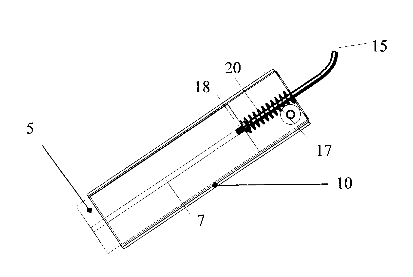
Figure 1 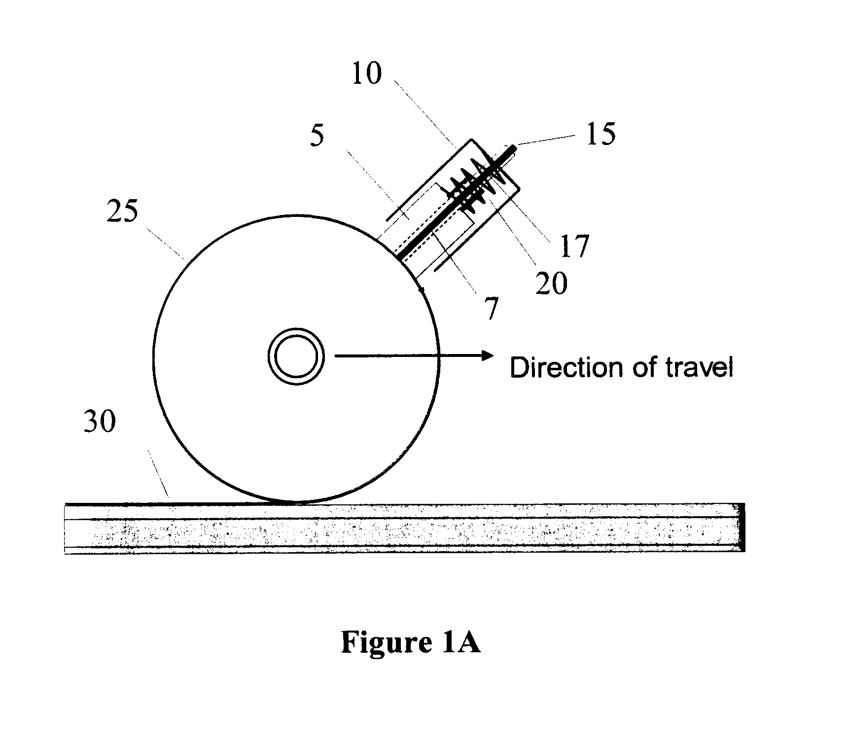
Figure 2 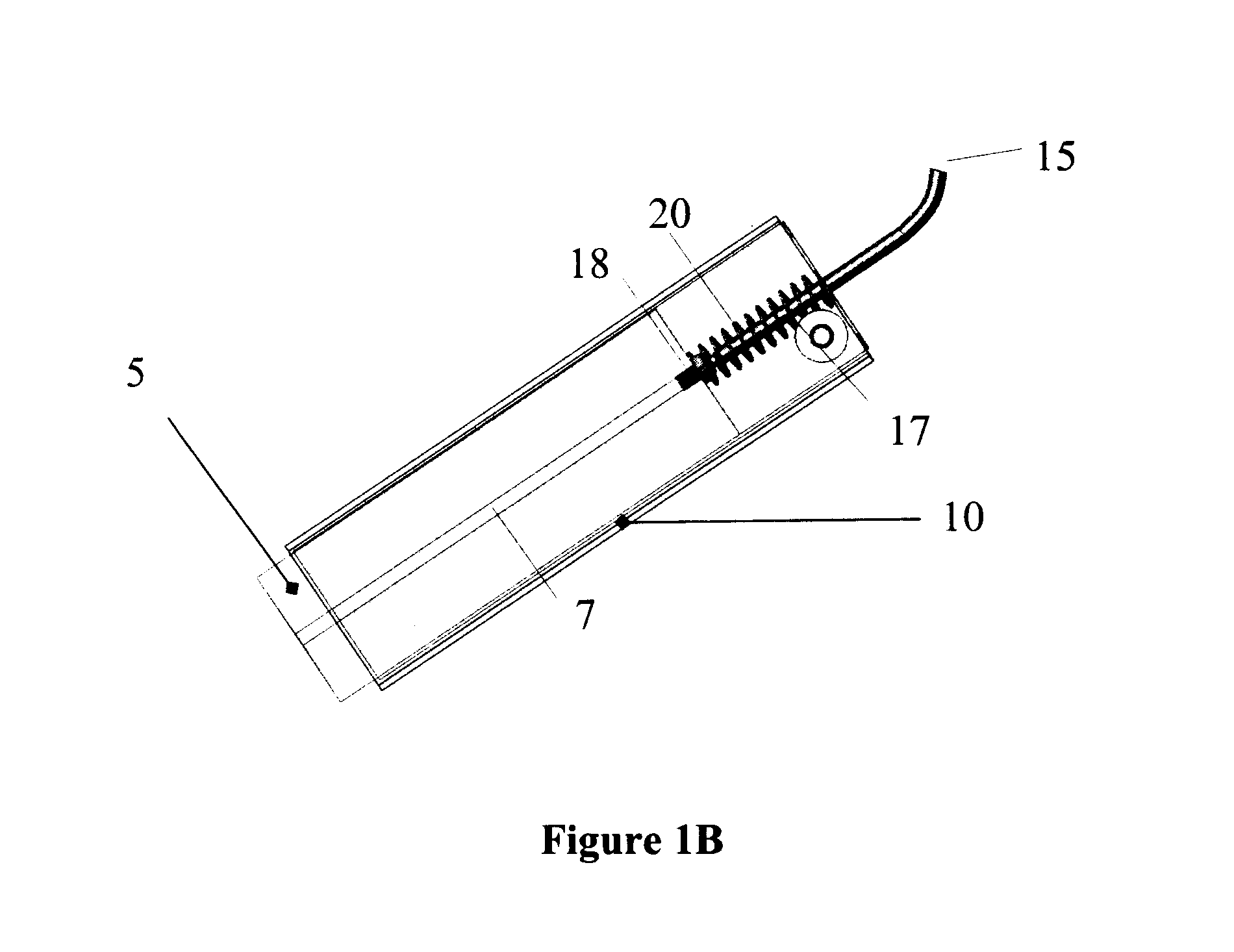
Figure 3
Abstract
Description
FIELD OF INVENTION
[0001] The present invention relates to a consumable applicator and methods for using the consumable applicator. The present invention also relates to a consumable applicator comprising friction control compositions and methods for using the consumable applicator.BACKGROUND OF THE INVENTION
[0002] Steel-rail and steel-wheel transportation systems including freight, passenger and mass transit rail systems suffer from the emission of high noise levels and extensive wear of mechanical components such as wheels, rails and other rail components such as ties. The origin of such noise emission, and the wear of mechanical components may be directly attributed to the frictional forces and behaviour that are generated between the wheel and the rail during operation of the system. The application of solid or liquid friction modifier compositions, to railroad tracks, wheel, or both, can significantly reduce the wear on both the railcar wheels and on the rails. Liquid friction mod...