System and method for resolving spatial orientation using intelligent optical selectivity

a spatial orientation and selectivity technology, applied in wave based measurement systems, instruments, transmission systems, etc., can solve the problems of high cost associated with these devices, easy damage, limitations of devices, etc., and achieve low cost, simple circuitry and optics, and low processing power

Inactive Publication Date: 2011-12-01
KRIETER MARCUS
View PDF11 Cites 3 Cited by
  • Summary
  • Abstract
  • Description
  • Claims
  • Application Information

AI Technical Summary

Benefits of technology

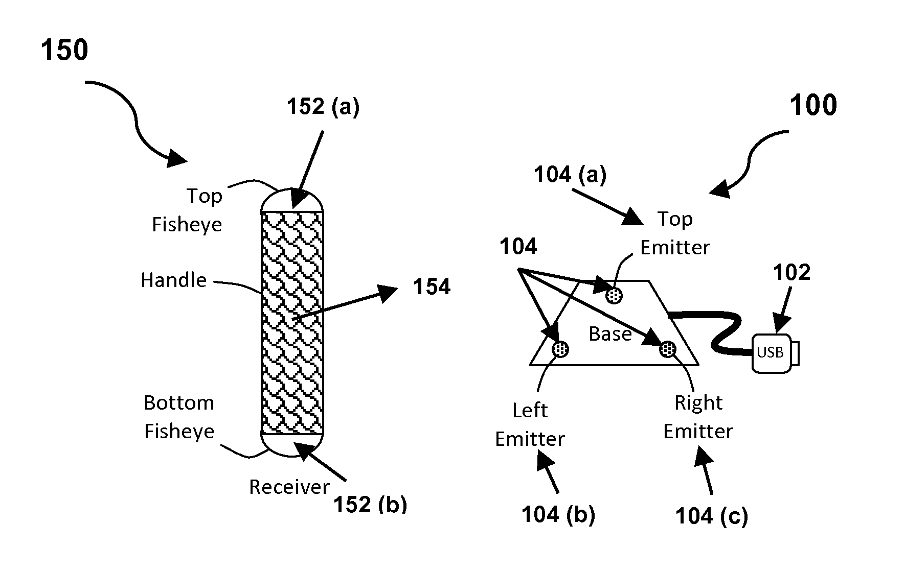
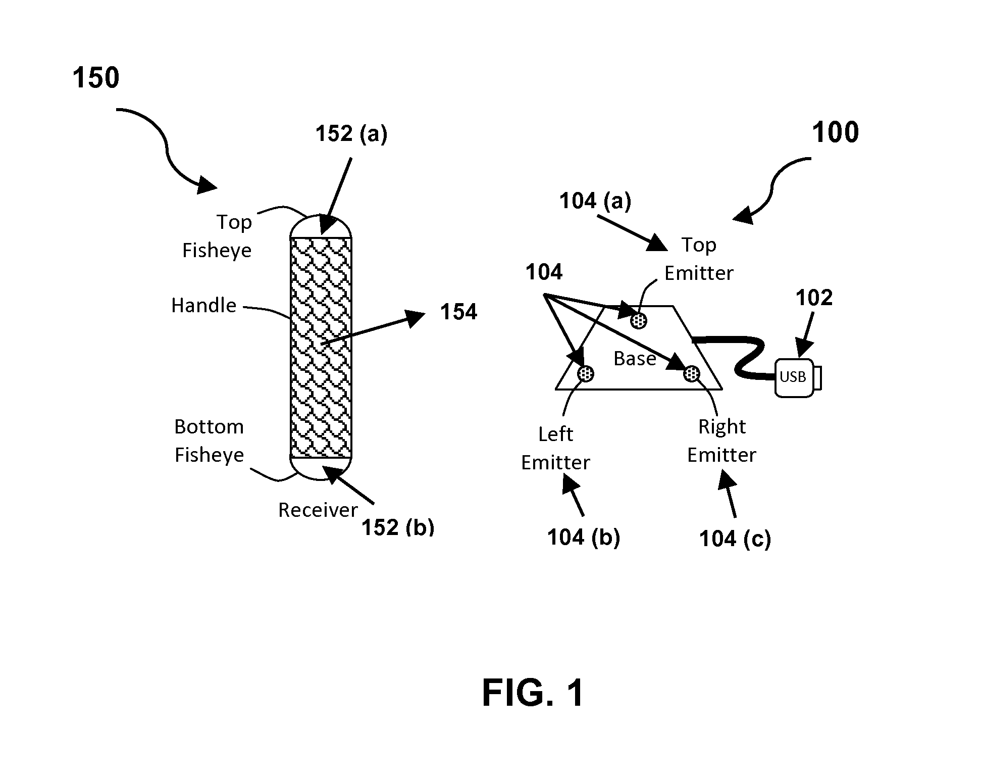
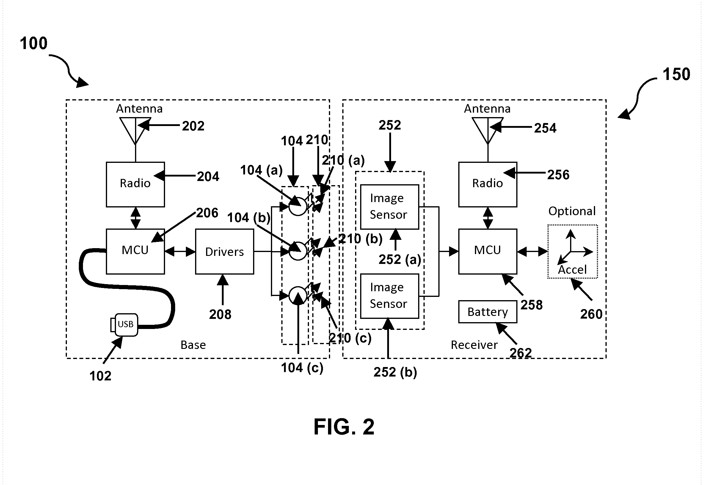
[0009]An object of the present invention is to provide a means to resolve complete free space orientation information of an active receiving device at high speed using simple circuitry and optics, and minimal processing power.

Problems solved by technology

However, these devices have limitations, and can be easily damaged because of their bulky size.
Further, the cost associated with these devices can be very high.
However, the standard CMOS sensor is susceptible to noise.
The limitations of the existing systems are not only that they provide limited abilities to resolve simple spatial orientations, but also, they are costly, bulky, require a large amount of processing power and use complex circuitry for operation.
As a result the device has a limited angle range for detection.

Method used


Image

  • System and method for resolving spatial orientation using intelligent optical selectivity
  • System and method for resolving spatial orientation using intelligent optical selectivity
  • System and method for resolving spatial orientation using intelligent optical selectivity

Examples


Embodiment Construction

[0027]In the following detailed description of the embodiments of the invention, numerous specific details are set forth in order to provide a thorough understanding of the embodiments of the invention. However, it will be obvious to one skilled in the art, that the embodiments of the invention may be practiced without these specific details. In other instances well known methods, procedures, components and circuits have not been described in detail so as not to unnecessarily obscure aspects of the embodiments of the invention.

[0028]Furthermore, it will be clear that the invention is not limited to these embodiments only. Numerous modifications, changes, variations, substitutions and equivalents will be apparent to those skilled in the art, without parting from the spirit and the scope of the invention.

[0029]The embodiments of the invention provide a system and method to resolve complete free space orientation information of an active receiving device at high speed using simple circ...


PUM


Abstract

The present invention provides a method and system for resolving complete free space orientation of an active receiving device at high speed using simple optics, trigonometry, simple circuitry, and using minimal processing power. The rapid triangulation of distance from the emitters, as well as resolution of rotational orientation, are determined by changing the contrast level in an infrared spectrum and by using wide angle lenses with greater than 180 degree hemispherical viewing angles. Furthermore, the system consists of an optional accelerometer, resident on the receiver, to dynamically adjust the image sensor frame rate.

Description

FIELD OF INVENTION[0001]The present invention relates to a method for resolving orientation information, and more particularly, to a method and system for rapidly detecting complete free space orientation of an active receiving device at high speeds, using an optical means.BACKGROUND[0002]‘Spatial Resolution’ describes the resolving power of any image-forming device and is expressed in a number of independent pixel values per unit of length. It is defined through various criteria such as the geometric properties of the imaging system and its ability to distinguish between target points. It depends on the properties of the system creating the image and not just the image resolution in pixels. For practical purposes, the clarity of the image is decided by its spatial resolution, and not the number of pixels in an image.[0003]For example, the Nintendo Wii remote controller, active laser range finders, and standard CMOS sensors are some commonly known systems used for spatial resolution...

Claims


Application Information

Patent Timeline
Patent Type & Authority Applications(United States)
IPC IPC(8): G06K9/00H04B7/00
CPCG01S5/163
Inventor KRIETER, MARCUS
Owner KRIETER MARCUS
Why Eureka
Try Eureka