Closed loop type fuel cell system with unreacted material removing function

Active Publication Date: 2011-12-01
KOREA INST OF MASCH & MATERIALS
View PDF1 Cites 3 Cited by
  • Summary
  • Abstract
  • Description
  • Claims
  • Application Information

AI Technical Summary

Benefits of technology

[0020]Another objective of the invention is to provide a closed loop type fuel cell system with unreacted material removing function, configured to selectively replace a sacrificial fuel cell provided in the regenerating means in order to inhibit decrease in the main fuel cell's electricity generating efficiency and so as to keep it from early breakage.
[0021]Another objective of the invention is to provide a closed loop type fuel cell system with unreacted material removing function that blocks the discharge of unreacted oxidant and reductant in order to inhibit unwanted accident such as explosion in the future.
[0038]Thus, a benefit of maximizing fuel efficiency is provided even when placed in a closed space such as a submarine. Electricity generation efficiency of the main fuel cell is also maximized by an action of the regenerating path.
[0039]Also, the present invention can advantageously block the early discharge of oxidant and reductant by an action of the exhausting means.
[0041]Thus, by selectively regenerating and enhancing electricity generation efficiency of the main fuel cell when such is lowered, a benefit of improving the durability of a main fuel cell is provided.
[0042]Moreover, as the present invention is configured to selectively replace a sacrificial fuel cell, the maintenance of a main fuel cell is easy and the maintainability of the sacrificial fuel cell can be improved.

Problems solved by technology

However, since the production of reactants is excessive, and supplying gas into the catalyst layer and diffusing proton into a polymer membrane are prohibited due to a plethora of moisture, in form of water droplets, produced within the operating environment of a high-current area inside a fuel cell, a lowering of fuel cells' performance is observed.
As a more significant problem, a partial cell performance drop on account of uneven water distribution per a unit cell existing in a fuel cell makes it difficult to perform a normal operation.
As such, considering the occurrence of excessive moisture in a fuel cell, referred to as flooding, is an important factor causing the lowering of reaction efficiency, and that it makes the secure operation of fuel cells difficult, it is desperately necessary to discharge excessive moisture out of a fuel cell.
Firstly, since a fuel purity supplied into a fuel cell fails to reach 100%; and thus, even if the gas separated from the moisture is re-supplied into the fuel cell, impurities stock up inside the fuel cell, lowering generation efficiency.
Also, when carbon, constructing a bipolar plate and an electrode, and impurities such as a metal ion and particles of a peripheral apparatus composing a fuel cell, stock up inside the fuel cell, gradually influencing the durability of the fuel cell as well as producing a current leakage inside it.
Consequently, this causes a lifetime shortening or breakage of the fuel cell and produces an enormous repair cost, which seems to be undesirable.
In addition, since a closed circuit is constructed, even if moisture produced in a fuel cell is removed by recirculating gas inside the fuel cell using a conventional technology, impurities influx inside the fuel cell again by means of the gas supplied into the fuel cell, lowering the performance and durability of fuel cells.

Method used


Image

  • Closed loop type fuel cell system with unreacted material removing function
  • Closed loop type fuel cell system with unreacted material removing function
  • Closed loop type fuel cell system with unreacted material removing function

Examples


Embodiment Construction

[0095]Hereinafter, a construction of a closed loop type fuel cell system will be described with regard to one embodiment, with reference to the accompanying drawings.

[0096]And, an embodiment of the present invention will be explained by applying oxygen as an oxidant and by using hydrogen as a reductant.

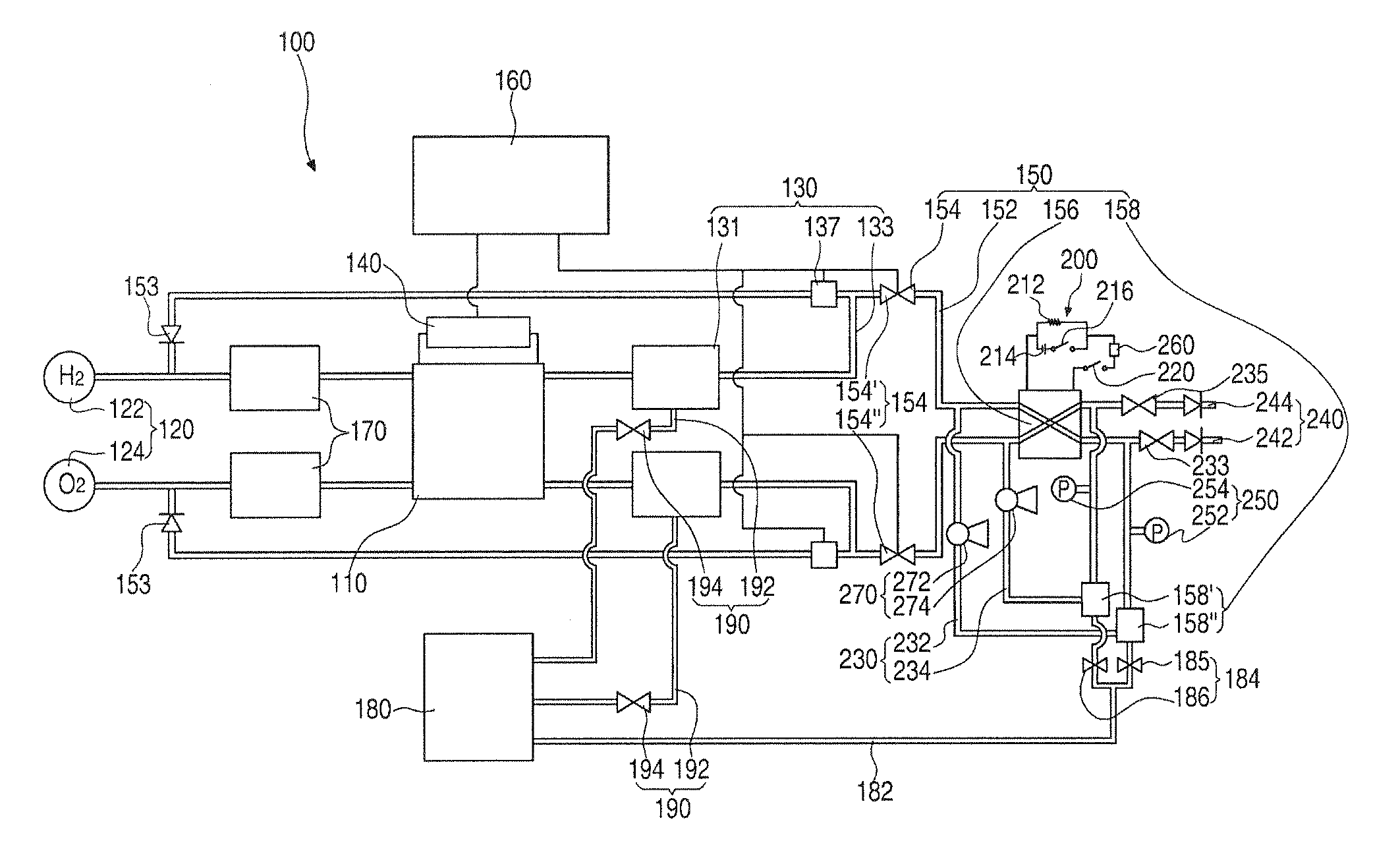
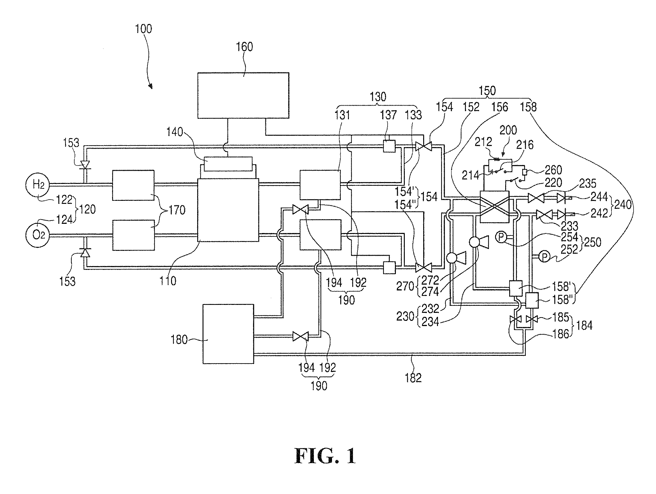
[0097]FIG. 1 shows a diagram showing a construction of a closed loop type fuel cell system according to the present invention.

[0098]As shown in the figure, a closed loop type fuel cell system 100 refers to a system that generates electricity by providing hydrogen (H2) and oxygen (O2) and oxidation-reduction reaction with them, including a main fuel cell 110; a supply means 120 supplying fuel containing hydrogen and oxygen for the main fuel cell 110; a recirculating means 130 recirculating fuel containing hydrogen and oxygen discharged from a main fuel cell 110 back into the main fuel cell 110; a detecting means 140 detecting voltages of a plurality of cells comprising the main fuel ce...


PUM


Abstract

Disclosed herein is a closed loop type fuel cell system having a removal function for an oxidant and a reductant, which are unreacted material, including a recirculating means recirculating oxidant and reductant discharged from the main fuel cell back into the main fuel cell; and a regenerating means for removing moisture produced during the operation of the main fuel cell and impurities contained in the recirculated oxidant and reductant.

Description

CROSS-REFERENCE TO RELATED APPLICATION[0001]This application claims the benefit under 35 U.S.C. §119 of Korean Application No. 10-2010-0049428, filed May 27, 2010, which is hereby incorporated by reference in its entirety.BACKGROUND OF THE DISCLOSURE[0002]1. Field of the Invention[0003]The present invention relates to a closed loop type fuel cell system with unreacted material removing function, including a recirculating means recirculating unreacted material, such as an oxidant and a reductant, discharged from the main fuel cell back into the main fuel cell; a regenerating means for removing moisture and impurities inside the main fuel cell; and an exhausting means for drawing out the oxidant and the reductant, which are unreacted materials existing inside the regenerating means.[0004]2. Description of Related Art[0005]A fuel cell refers to a system that generates electricity through the reaction of oxygen and fuel (LNG, LPG, hydrogen, methanol, etc.), and simultaneously produces w...

Claims


Application Information

Patent Timeline
IPC IPC(8): H01M8/06
CPCY02E60/50H01M8/06H01M8/0662H01M8/04097H01M8/04761H01M8/0438H01M8/04552H01M8/04559H01M8/04753H01M8/04164
Inventor YANG, CHEOL NAMLEE, CHANG RAE
Owner KOREA INST OF MASCH & MATERIALS
Why Eureka
Try Eureka