
Rapid de-excitation system for synchronous machines with indirect excitation

Inactive Publication Date: 2011-12-08
UNIV MADRID POLITECNICA
View PDF5 Cites 15 Cited by
  • Summary
  • Abstract
  • Description
  • Claims
  • Application Information

AI Technical Summary

Benefits of technology

The system object of the present invention allows a synchronous indirect excitation machine to behave for deexcitation purposes similarly to a direct excitation machine, but maintaining the advantages of brushless excitation.
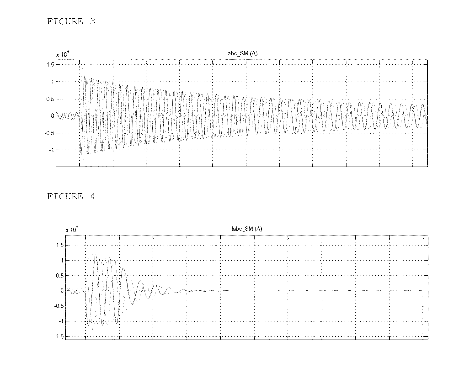
As a result of the system thus described, in the event of an internal defect of the synchronous machine, the damage is limited. In a synchronous machine with conventional indirect excitation, the fault current in the event of an internal short circuit can last in the order of several seconds with the subsequent damage for the alternator. However, by implementing the deexcitation system object of the invention, this time is considerably reduced, minimizing the damage.

Problems solved by technology

When internal short circuits occur in a generator, or before the generator switch, damage occurs due to the contribution to the short circuit by the generator itself.
The brushes wear with use and must be replaced and maintained.
Also the sparks and carbon dust deposits are always a focal point of possible problems.
The brush problem is eliminated with indirect excitation, but it has the drawback of worsening the dynamic response of the machine since it does not have direct access to the excitation winding of the main generator because it uses an intermediate element, another electric machine, i.e., the exciter.
This is not as easy in indirect excitation machines by means of rotating diodes, where there is no direct access to the excitation winding.

Method used


Image

  • Rapid de-excitation system for synchronous machines with indirect excitation
  • Rapid de-excitation system for synchronous machines with indirect excitation
  • Rapid de-excitation system for synchronous machines with indirect excitation

Examples


Embodiment Construction

The system object of the present invention allows a synchronous indirect excitation machine to behave for deexcitation purposes similarly to a direct excitation machine, but maintaining the advantages of brushless excitation.

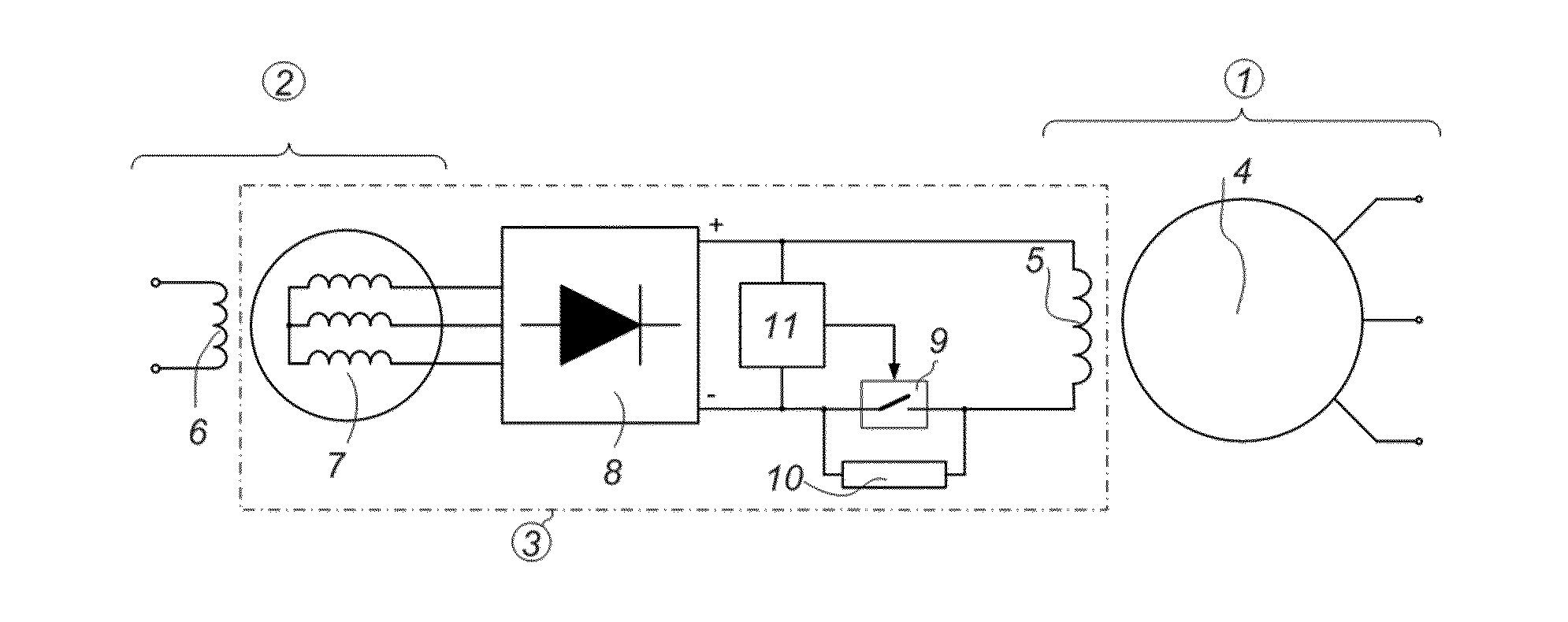
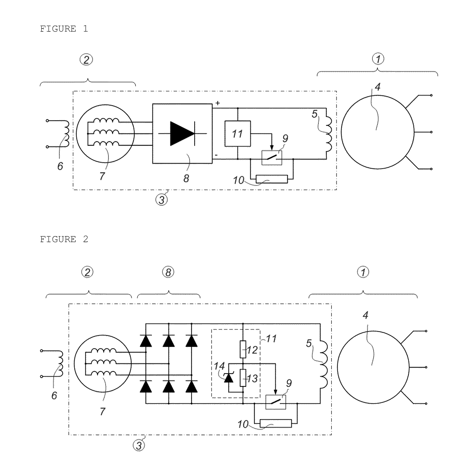
The rapid deexcitation system for synchronous machines with indirect excitation by means of an excitation machine and rotating rectifier bridge comprises:a deexcitation impedance, preferably a resistor, connected between the field winding of the synchronous machine and the rotating rectifier bridge;a controller, preferably a semiconductor-type controller, connected in parallel with the deexcitation impedance;a control circuit of the controller configured to:keep the controller closed such that the rotating rectifier bridge directly feeds the field winding of the synchronous machine during normal operation of the synchronous machine;deexcite the synchronous machine (in the event of a short circuit or in the event of the disconnection of the synchronous machine fr...


PUM


Abstract

The invention relates to a rapid deexcitation system for synchronous machines (1) with indirect excitation by means of an excitation machine (2) and rotating rectifier bridge (8) comprising:a deexcitation impedance (10) connected between the field winding (5) of the synchronous machine (1) and the rotating rectifier bridge (8);a controller (9) connected in parallel with the deexcitation impedance (10);a control circuit (11) of the controller (9) configured to:keep the controller (9) closed such that the rotating rectifier bridge (8) directly feeds the field winding (5) of the synchronous machine (1) during normal operation of the synchronous machine (1);open the controller (9) such that the deexcitation impedance (10) remains in series with the field winding (5) and with the rotating rectifier bridge (8) when the synchronous machine is to be deexcited.

Description

The object of the present invention patent is to provide a new deexcitation system for synchronous machines with indirect excitation by means of rotating diodes, whereby improving the dynamic response and safety when deexciting the machine, which means that in the event of an internal short circuit the damage to the machine would be much less.BACKGROUND OF THE INVENTIONWhen internal short circuits occur in a generator, or before the generator switch, damage occurs due to the contribution to the short circuit by the generator itself. In this case it is essential to reduce the excitation current as quickly as possible, such that voltage is not induced in the stator and therefore there is no more contribution to the short circuit.There are essentially two types of excitation for synchronous machines:Direct excitation by means of collector rings and brushes.Indirect brushless excitation by means of an excitation machine and rotating diodes.The brushes and the collector rings are element...

Claims


Application Information

Patent Timeline
IPC IPC(8): H02P9/10
CPCH02P9/10H02P9/302H02P9/102H02K19/38H02P9/12H02P9/126
Inventor PLATERO GAONA, CARLOS ANTONIOBLAZQUEZ GARCIA, FRANCISCOFRIAS MARIN, PABLOREDONDO CUEVAS, MARTAGRANIZO ARRABE, RICARDOCARRERO LOPEZ, CAMELO
Owner UNIV MADRID POLITECNICA
Learn More