
Method of Transmitting and receiving Data in a Wireless System

a wireless communication and wireless technology, applied in the direction of synchronization arrangement, transmission path division, broadcast with distribution, etc., can solve the problems of inability to solve the delay differences of signals received from a plurality, difficult to implement comp (coordinated multi-point) schemes, and inability to synchronize signals received from multiple points

Inactive Publication Date: 2011-12-15
LG ELECTRONICS INC
View PDF10 Cites 32 Cited by
  • Summary
  • Abstract
  • Description
  • Claims
  • Application Information

AI Technical Summary

Benefits of technology

The present invention provides a method for transmitting data in a wireless communication system, which overcomes the problem of timing error caused by signals received from multiple cells. The method involves receiving information on the delay times of signals from the mobile station and transmitting data to the mobile station by inserting a cyclic prefix into the data. This allows for the synchronization of signals from multiple cells and improves the performance of the system. The invention also includes methods for generating a time domain signal and a frequency domain signal for transmitting data to the mobile station. Overall, the invention provides a method for transmitting data in a wireless communication system that solves the problem of timing error and improves system performance.

Problems solved by technology

Specifically, when a receiving stage receives signals from multiple points located physically existing at different locations, the signals received from the multiple points may not be synchronized with each other.
Due to this reason, it is difficult to implement CoMP (coordinated multi-point) schemes.
Yet, if the signals received from a plurality of the cells differ from each other in delay, it is unable to solve the delay differences of the signals received from a plurality of the cells using inter-symbol interference correction in consideration of a delay spread of a single-cell system.
In OFDM system, timing / frequency error considerably affects system performance.
Yet, since the CoMP scheme considerably affects the timing error, when a receiving stage receives a signal, performance can be seriously degraded.

Method used


Image

  • Method of Transmitting and receiving Data in a Wireless System
  • Method of Transmitting and receiving Data in a Wireless System
  • Method of Transmitting and receiving Data in a Wireless System

Examples


first embodiment

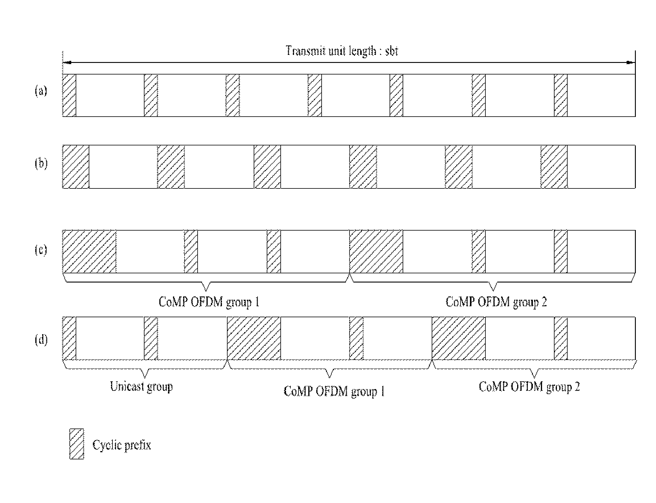
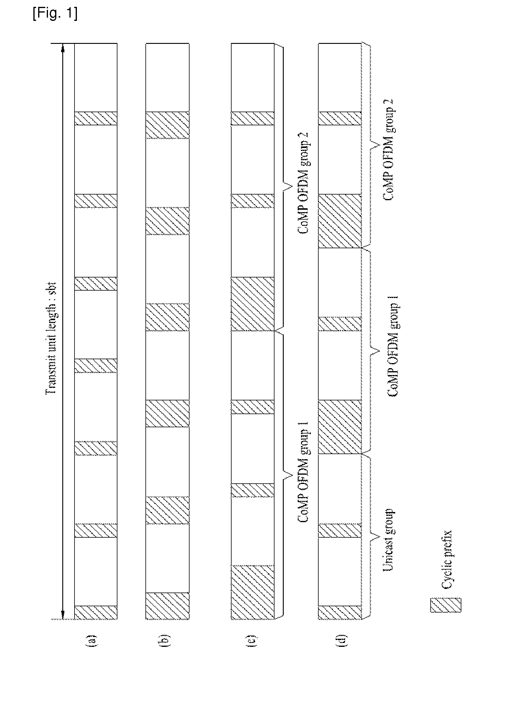
[0037]A method of transmitting data according to the present invention is explained with reference to FIG. 1 as follows.

[0038]First of all, in a single cell environment, a CP length is set in consideration of a delay spread of signal only. In this case, the delay spread of signal is affected by a geographical environment of a cell. In a single cell environment, a CP is used to supplement a round trip delay and a multipath delay and performs timing advance using a random access channel (RACH), whereby a system can operate without problems. Yet, in a multi-cell environment, it is necessary to supplement a propagation delay of signal, i.e., a delay time taken for a signal containing significant energy therein to come in as well as the multipath delay.

[0039]According to a first embodiment of the present invention, a CP length is set longer than that of a single cell environment and is also set to supplement a maximum signal delay time of a system.

[0040]A plurality of cells in progress o...

second embodiment

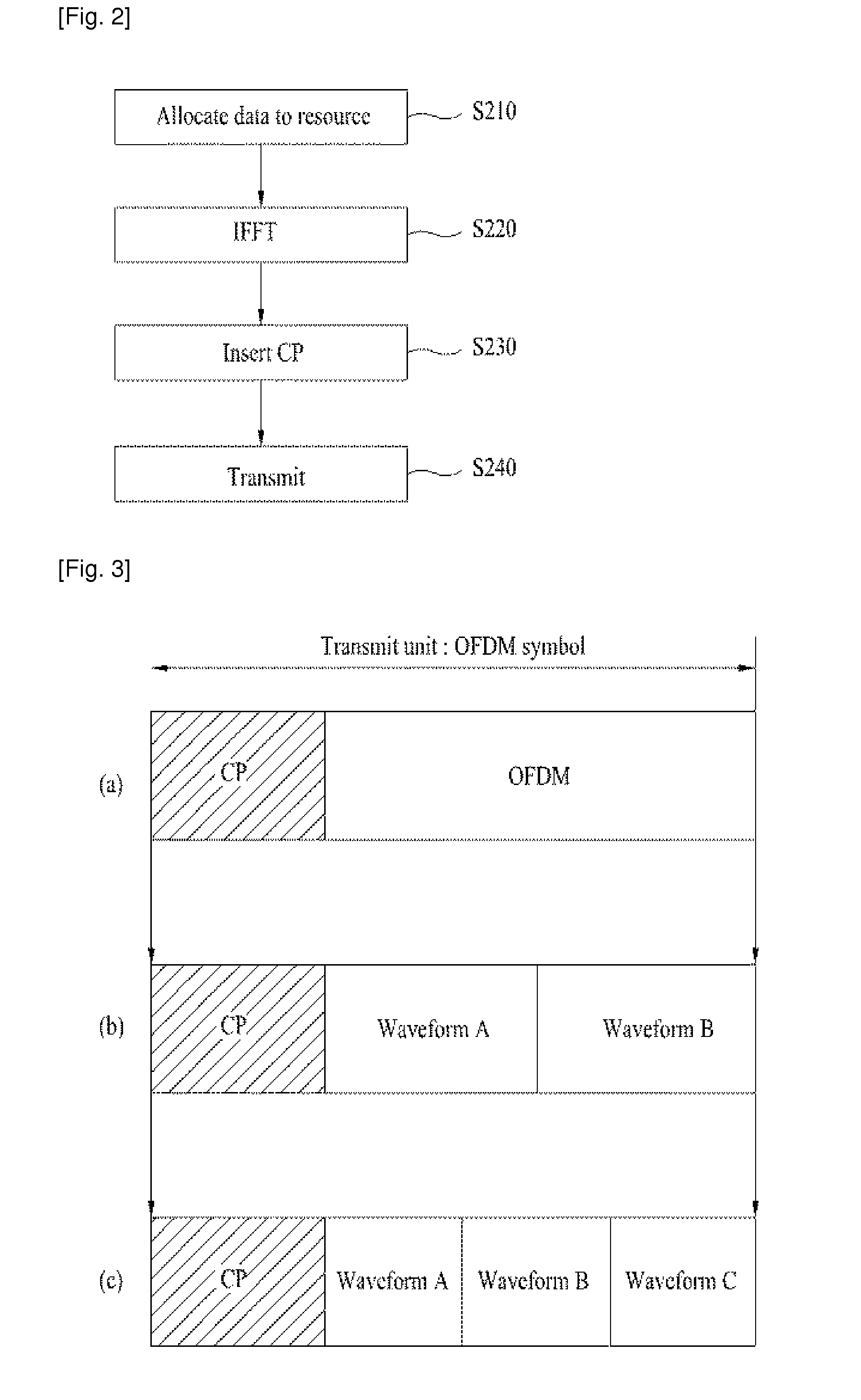
[0054]In the following description, a method of transmitting data according to the present invention is explained with reference to FIG. 2 and FIG. 3.

[0055]According to a second embodiment of the present invention, a multiplexing method for bringing an effect of extending a CP length is used. According to a second embodiment of the present invention, a signal is rendered to repeatedly appear in a time domain to use a portion of the repeated signal as a cyclic prefix or a cyclic postfix.

[0056]FIG. 2 is a flowchart of a data transmitting method according to a second embodiment of the present invention.

[0057]Referring to FIG. 2, a base station allocates data, which will be transmitted, to a resource region [S210]. In doing so, the base station allocated the data to the resource region with an interval of at least two subcarriers. If the data to transmit is allocated on a frequency axis with 2-subcarrier interval, a corresponding OFDM symbol generates a waveform repeated twice on a time...

third embodiment

[0066]In the following description, a method of transmitting data according to the present invention is explained with reference to FIG. 4 and FIG. 5.

[0067]According to a third embodiment of the present invention, while a related art OFDM symbols structure is maintained, a process different from that of a resource for supporting a user equipment communicating with a single cell is applied to a resource for supporting CoMP.

[0068]FIG. 4 is a diagram for a data allocating process according to a third embodiment of the present invention.

[0069]Referring to FIG. 4, a base station arranges data in a single carrier transmission format in a time domain and then inserts a cyclic prefix and / or a cyclic postfix in front and / or rear of the data.

[0070]In doing so, after the cyclic prefix or the cyclic postfix has been inserted, if signals having different delay times are received, it is able to maintain orthogonality of a corresponding OFDM symbol. If both of the cyclic prefix and the cyclic post...


PUM


Abstract

A method of transmitting data in a wireless communication is disclosed, by which timing error can be solved in a multi-cell environment. The present invention, in which data is transmitted by a serving cell to a mobile station communicating with a plurality of cells in a wireless communication system, includes receiving information on delay times of signals from the mobile station, wherein the signals are received by the mobile station from the plurality of the cells and transmitting data to the mobile station by inserting a cyclic prefix (CP) having a length determined according to the information on the delay times into the data.

Description

TECHNICAL FIELD[0001]The present invention relates to a wireless communication system, and more particularly, to a method of transmitting data in a wireless communication system.BACKGROUND ART[0002]The present invention relates to a method of overcoming a delay of signal in an environment in which the signal delay takes place.[0003]As a representative example of generating a signal delay, there is a coordinated multi-point (hereinafter abbreviated CoMP). Specifically, when a receiving stage receives signals from multiple points located physically existing at different locations, the signals received from the multiple points may not be synchronized with each other. For instance, when a base station existing at one location simultaneously transmits signal into multi-cell identified at the corresponding point, timing ambiguity or delay tends not to occur. On the contrary, in case that signals are transmitted / received to / from physically different locations, different delays are experien...

Claims


Application Information

Patent Timeline
Patent Type & Authority Applications(United States)
IPC IPC(8): H04W56/00
CPCH04L5/0007H04L5/0032H04W56/003H04L5/0044H04L27/2607H04L5/0035
Inventor KWON, YEONG HYEONCHUNG, JAE HOONKOO, JA HOKO, HYUN SOO
Owner LG ELECTRONICS INC
Learn More