Stable Millimeter Wave Source for Broadband Wireless Signal Transmission Using Optical Fibre

Inactive Publication Date: 2011-12-15
TELEKOM MALAYSIA BERHAD
View PDF1 Cites 6 Cited by
  • Summary
  • Abstract
  • Description
  • Claims
  • Application Information

AI Technical Summary

Benefits of technology

[0005]It is an object of the present invention to provide an apparatus and method for the stable generation of a millimetre wave source using a Stimulated Brillouin Scattering (SBS)

Problems solved by technology

However, the process of generating the millimetre wave in the optical domain has the problem of stability because any small wavelength changes in the optical domain, is translated into a substantial frequency dev

Method used


Image

  • Stable Millimeter Wave Source for Broadband Wireless Signal Transmission Using Optical Fibre
  • Stable Millimeter Wave Source for Broadband Wireless Signal Transmission Using Optical Fibre
  • Stable Millimeter Wave Source for Broadband Wireless Signal Transmission Using Optical Fibre

Examples


Embodiment Construction

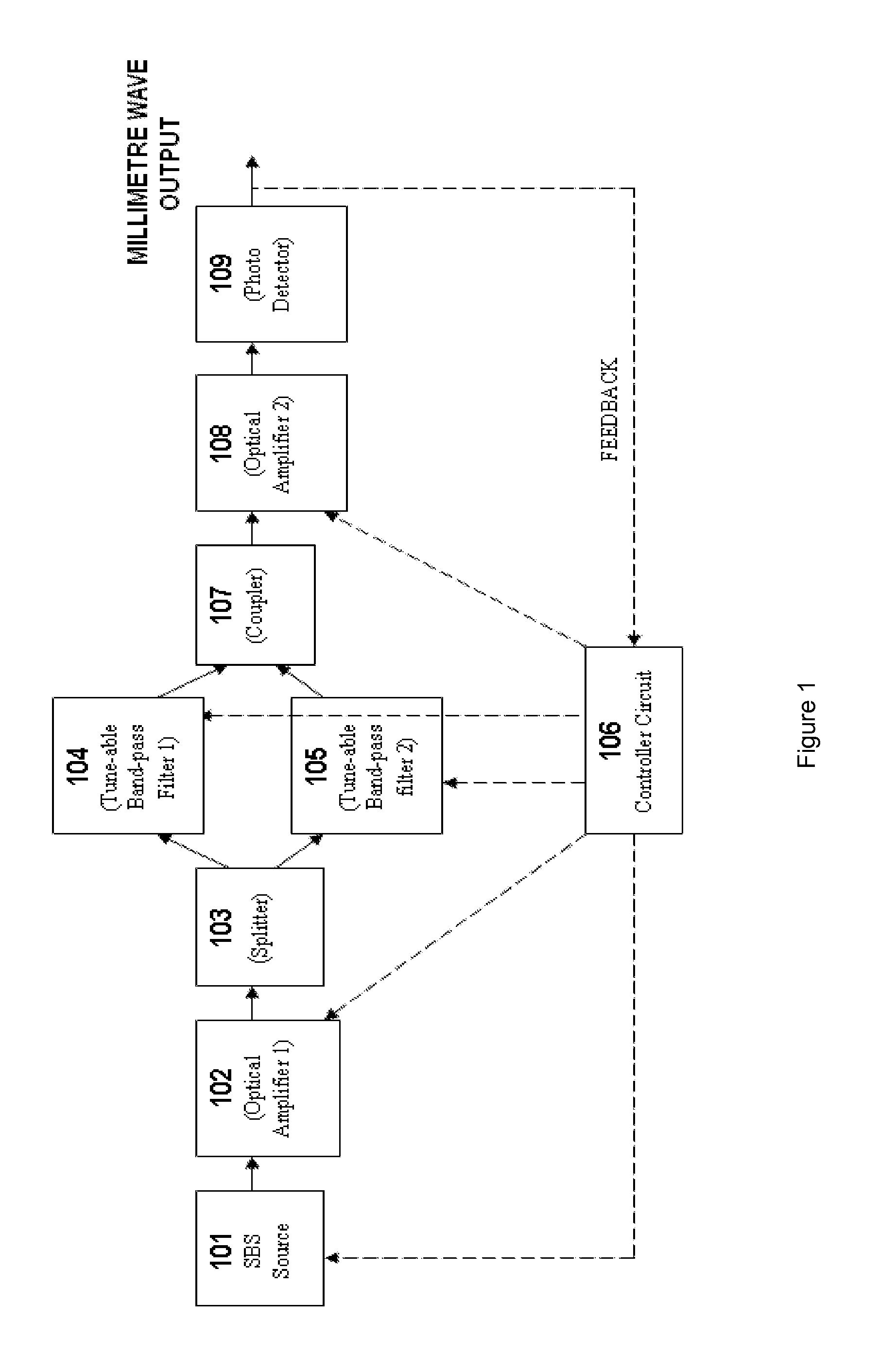
[0022]Referring to FIG. 1, a stable millimetre wave source of the present invention consists of a Stimulated Brillouin Scattering (SBS) source 101, a first optical amplifier 102, a splitter 103, a first tuneable band-pass filter 104, a second tuneable band-pass filter 105, a controller circuit 106, a coupler 107, a second optical amplifier 108 and a photo detector 109.

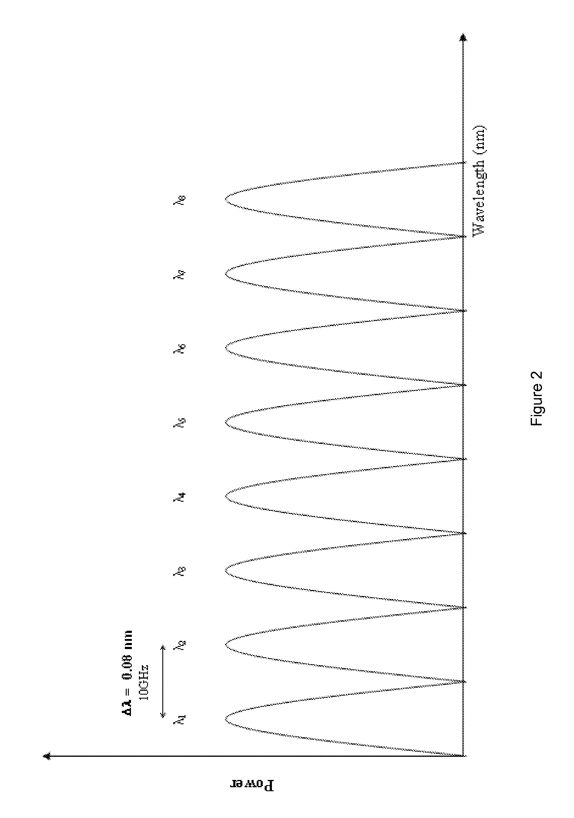
[0023]The SBS source 101 is designed to produce an optical signal that is in itself composed of a multi-stokes light wave signal of various wave-lengths. This optical signal of various wavelengths with multi stokes light wave signal is split into two optical signals of equal proportions, i.e. two optical signals of identical magnitude, frequency, phase and electromagnetic mode. The first tuneable band-pass filter 104 and the second tuneable band-pass filter 105 extract the relevant stokes to provide two independent optical outputs which are then combined by the coupler 107. The combined optical signal has a dual stoke ...


PUM


Abstract

An apparatus and method for generating a millimetre-wave carrier signal for optical data transmission is disclosed. The apparatus includes stimulated Brillouin scattering source (101) that generates a variable stoke line multi-wavelength optical signal, optical amplifiers (102, 108), an optical splitter (103) that splits the amplified output of the SBS source (101) into two identical optical signals of the same magnitude, frequency, phase and electromagnetic mode, identical optical tuneable band-pass filters (104, 105) with the same band-pass, an optical coupler (107) that combines the optical signals emitted from the output of the optical filters (104, 105) such that the output of the coupler (107) is a dual wavelength optical signal with a wavelength separation equivalent to the desired millimetre wave frequency, a photo-detector (109) that converts the optical signal to an electrical signal by heterodyning process, and a controller circuit (106) that controls the gain of the optical amplifiers (102, 108), the tuning of the optical band-pass filters (104, 105) independently and the number of stoke lines produced by the stimulated Brillouin scattering source (101) depending on the electrical millimetre wave output.

Description


Claims


Application Information

Patent Timeline
Owner TELEKOM MALAYSIA BERHAD
Why Eureka
Try Eureka