Device for providing a flow of active gas

a technology of active gas and gas supply, which is applied in the direction of funeral devices, dental surgery, dental tools, etc., can solve the problems of reducing the size of the gas source in the hand-held consumer device, reducing the flow at other areas, and reducing the space between the electrodes. , to achieve the effect of reducing the spacing and preserving gas and power

Inactive Publication Date: 2011-12-15
LINDE AG
View PDF2 Cites 15 Cited by
  • Summary
  • Abstract
  • Description
  • Claims
  • Application Information

AI Technical Summary

Benefits of technology

[0011]In a first preferred aspect of the invention, the electrode configuration maintains glow discharge and generally avoids arcing between the electrodes. In this way, homogeneity of plasma generation can be increased which conserves both power and gas. The electrodes may comprise electrical conductors or barrier to barrier capacitive coupled electrodes.
[0012]One way in which this can be achieved is by the arrangement of at least one of said electrodes so that it comprises an array of electrode portions, each of which in use energises gas in the plasma forming region, wherein the electrode portions are distributed over said plasma forming region for increasing homogeneity of plasma generation of gas flowing through the plasma cell. This arrangement reduces the occurrence of arcing since there are many electrode portions and therefore arcing at any one portion of the electrode is reduced.
[0013]In a preferred array, said electrode portions comprise respective electrical conductors which in use transmit electrical charge to gas flowing through the cell and each electrode portion comprises an electrical resistor connected between the electrical conductor and the source of electrical energy so that when any one first electrode portion generates plasma in the plasma forming region, the electrical potential is reduced by the flow of current through the resistor of said first electrode portion so that the potential at the other of the electrode portions is higher than at said first electrode portion. Accordingly, electrical energy is diverted from an electrode portion which has already generated to plasma to those electrodes which have yet to generate plasma. There are two benefits of this arrangement. First, when electrode portion has ignited plasma it requires less energy for sustaining the plasma. Second, it reduces the concentration of current at any one electrode which may lead to arcing and reduced efficiency of gas usage.
[0017]In alternative arrangement for making efficient use of gas flow through the plasma cell, the plasma forming region is generated in use by arcing between the electrodes and the cell and the location of the electrodes is configured so that a substantial portion of gas flowing through the cell passes through said plasma forming region for increasing homogeneity of plasma generation. Although in this arrangement arcing occurs, the location of the arcing is controlled so that it is in the flow path of the gas and substantially all of the gas flows through the energised region where arcing occurs. Accordingly, homogeneity of plasma generation can be achieved.
[0019]A predetermined flow of plasma is generally required for beneficial treatment of a treatment region. A miniaturised plasma cell is advantageous in that it is able to supply this beneficial flow but also conserve gas and power to the extent possible. In a miniaturised plasma cell, the spacing between the electrodes is reduced, preferably to no more than 10 mm. In some arrangements, the electrode spacing can be considerably less than 10 mm and may be as little as 0.1 mm. The reduced spacing reduces power usage because all of the gas passing through the plasma forming region between the electrodes is exposed to substantial amounts of energy. In this regard, plasma generation may occur more readily in the volume of the plasma generating region proximate the electrode surfaces and therefore reduced spacing increases the efficiency of plasma production per unit of energy supplied. The plasma cell may have a free gas space of between 1 and 5 ml or less.
[0020]In another possible arrangement, a miniature array of miniature plasma cells is provided which each receive in use gas from a source of gas and a plurality of said electrodes for energising gas in the plasma cells to generate a plasma. This arrangement reduces the propensity of current hogging at any one electrode and therefore improves homogeneity of plasma production.

Problems solved by technology

Once current begins to flow there is a cascade effect which increases plasma generation at this small portion but deprives the flow at other areas of the electrodes.
Given that the size of a gas source in a hand-held consumer device is limited, gas must be used efficiently to prolong the life of the device between refills.

Method used


Image

  • Device for providing a flow of active gas
  • Device for providing a flow of active gas
  • Device for providing a flow of active gas

Examples


Embodiment Construction

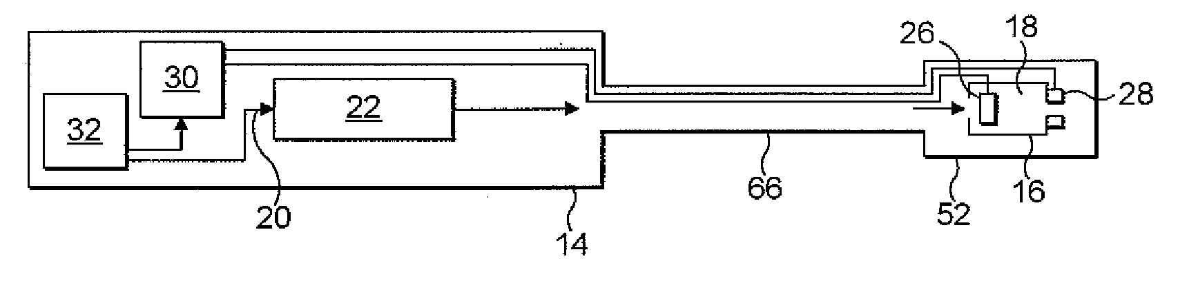
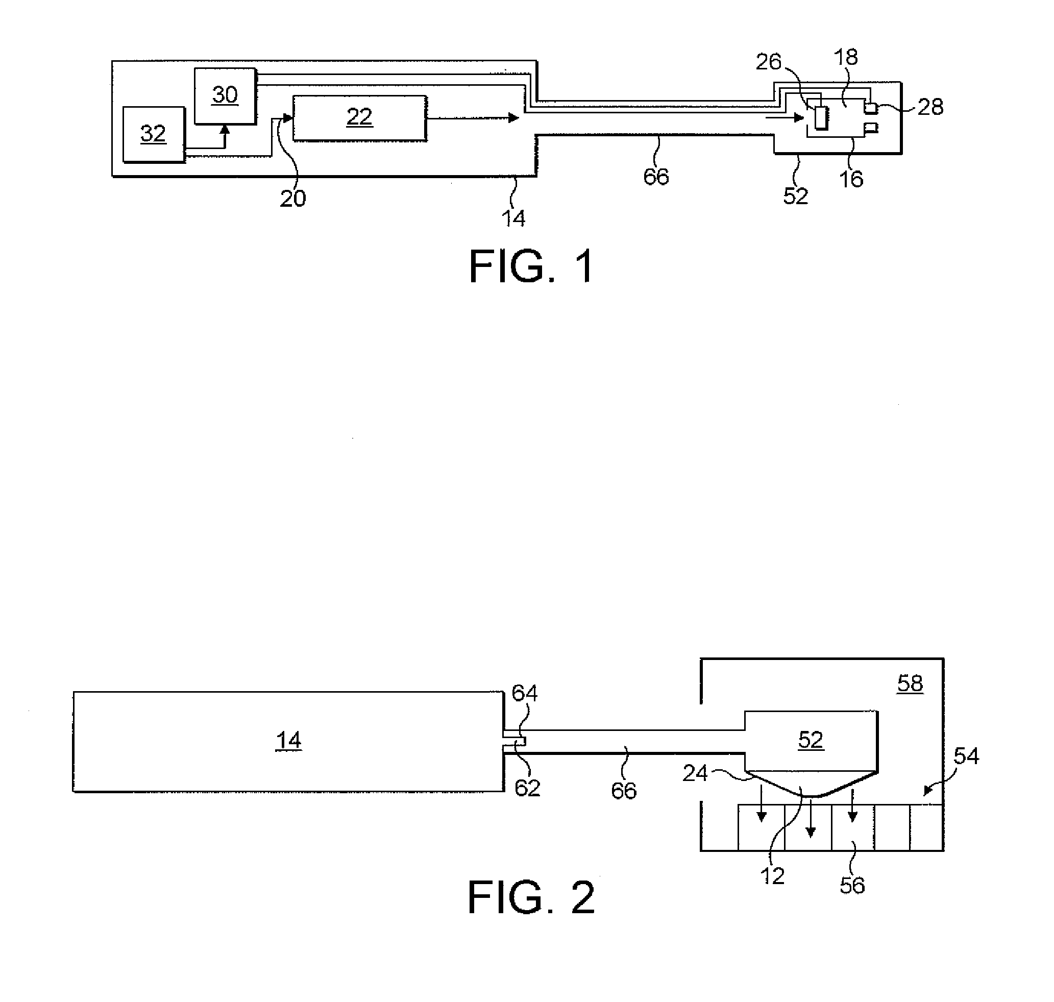
[0028]Referring to FIGS. 1 and 2, a device 10 is shown for generating a non-thermal gaseous plasma from a gas stream. Referring to FIG. 2, gas plume 12 containing ions and other chemically active species is emitted from the device. The device is configured to be hand-held and operated and therefore should be of a mass, size and shape enabling a typical user of the device to operate the device for treating a treatment region.

[0029]The device 10 comprises a housing 14 configured to be held by hand and in which the components of the device are housed. The housing also provides electrical insulation from high electrical potentials generated within the housing during use of the device.

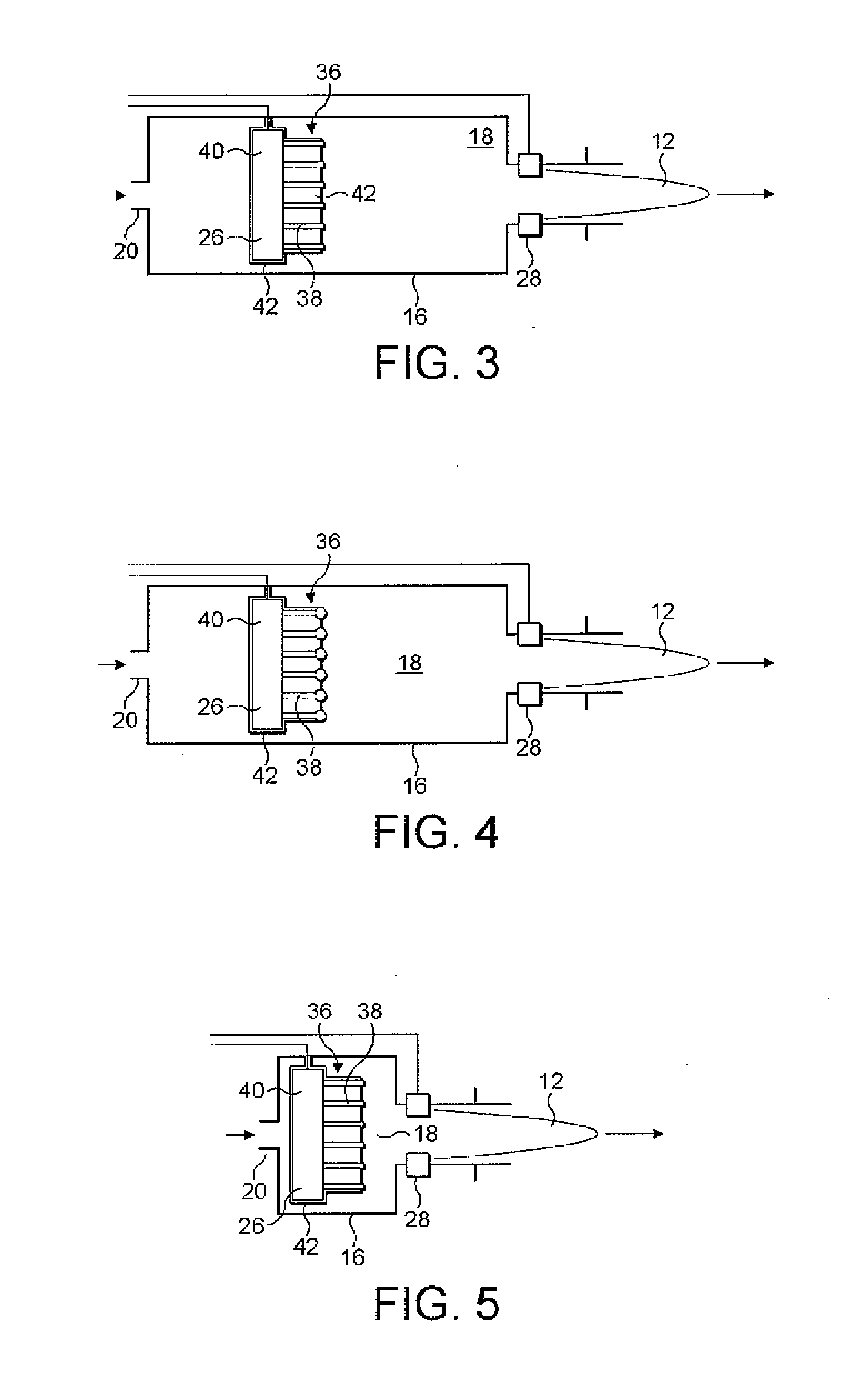
[0030]A miniature plasma cell 16 defines a plasma forming region or volume 18 in which gas passing through a cell inlet 20 from a gas source 22 can be energised to form a non-thermal gaseous plasma and discharged through a cell outlet 24 for treatment of a treatment region by the resulting gaseous plume. Th...


PUM


Abstract

A device 10, typically hand-held, provides a flow of partially ionised gaseous plasma for treatment of a treatment region. The device comprises an applicator head 52 housing a miniature plasma cell 16 in which gas flowing through the cell from a gas source 22 can be energised to form a non-thermal gaseous plasma, and a plurality of electrodes 26, 28 for receiving electrical energy from a source of electrical energy for energising gas in a plasma forming region 18 in the cell to form said plasma. The applicator head 52 is detachable from the device and may be of a size and configuration to enable it to be inserted into the oral cavity of a human or animal.

Description

BACKGROUND OF THE INVENTION[0001]The present invention relates to a device for providing a flow of active gas. In particular the invention is directed towards a device used which generates non-thermal plasma for treating an oral region of a human or animal body.[0002]Systems for the generation of non thermal gas plasmas are known and have utility in a number of fields such as industrial, dental, medical, cosmetic and veterinary fields for the treatment of the human or animal body. Non-thermal gas plasma generation can be employed to promote coagulation of blood, cleaning, sterilisation and removal of contaminants from a surface, disinfection, reconnection of tissue and treatment of tissue disorders without causing significant thermal tissue damage.[0003]Hereto, the application of non-thermal plasmas has been confined to controlled environments, such as in industry or clinics, since there is risk associated with the generation of plasmas with high electrical potentials, which if tran...

Claims


Application Information

Patent Timeline
Patent Type & Authority Applications(United States)
IPC IPC(8): A61C19/00A61C3/00
CPCA61B18/042H05H1/24A61C17/02H05H2240/10H05H2240/20H05H1/46H05H1/4697H05H2245/60H05H2245/32
Inventor HOLBECHE, THOMAS BICKFORDREICH, RICHARD THOMASDOBSON, PETERDEVERY, CORMAC JOHNTATAREK, ANDREW RICHARD THOMAS
Owner LINDE AG
Why Eureka
Try Eureka