Disconnect device for downhole assembly

a technology of disconnect device and assembly, which is applied in the oil and gas industry, can solve the problems of inability to recover the bha, inability to use the bha, so as to prevent the pinion from rotating again

Active Publication Date: 2011-12-22
INTELLIGENT DRILLING TOOLS
View PDF4 Cites 38 Cited by
  • Summary
  • Abstract
  • Description
  • Claims
  • Application Information

AI Technical Summary

Benefits of technology

[0033]Alternatively, said actuator comprises the sleeve being screw threaded on said first part and having a circumferential rack driven by a pinion of a motor, whereby screwing of the sleeve on the first part moves it axially between said operational and disconnect positions. Preferably, said pinion is threaded on a coarsely threaded output shaft of the motor and is translatable along said shaft between driving and secured positions, in the driving position it being engaged only with said rack whilst in the secured position it being engaged with a block of the sleeve preventing further rotation of the pinion whilst permitting axial movement thereof.
[0034]The above described embodiment of the invention provides reliable means for retaining the first and second parts of the disconnect tool together under normal operating conditions and allows for a mechanical separation upon actuation of the actuator. The above arrangement provides disconnect means that does not explosively sever components and therefore does not damage the drill string. Drilling can recommence quickly, therefore, as soon as a new BHA is attached.

Problems solved by technology

However, in situations where recovery of the BHA is impractical or impossible, the stuck BHA will be abandoned and drilling will recommence along a different route with a new BHA attached to the drill string.
However, this is often impossible when the BHA becomes stuck.
This technique is often complicated and difficult and is consequently unreliable.
Due to the high operating costs of drill rigs, this significant time period of non-operation can lead to substantial financial losses which are highly undesirable.
It follows that explosive disconnection is generally not an option for the disconnection of a BHA in a horizontal section of the well bore.

Method used


Image

  • Disconnect device for downhole assembly
  • Disconnect device for downhole assembly
  • Disconnect device for downhole assembly

Examples


Embodiment Construction

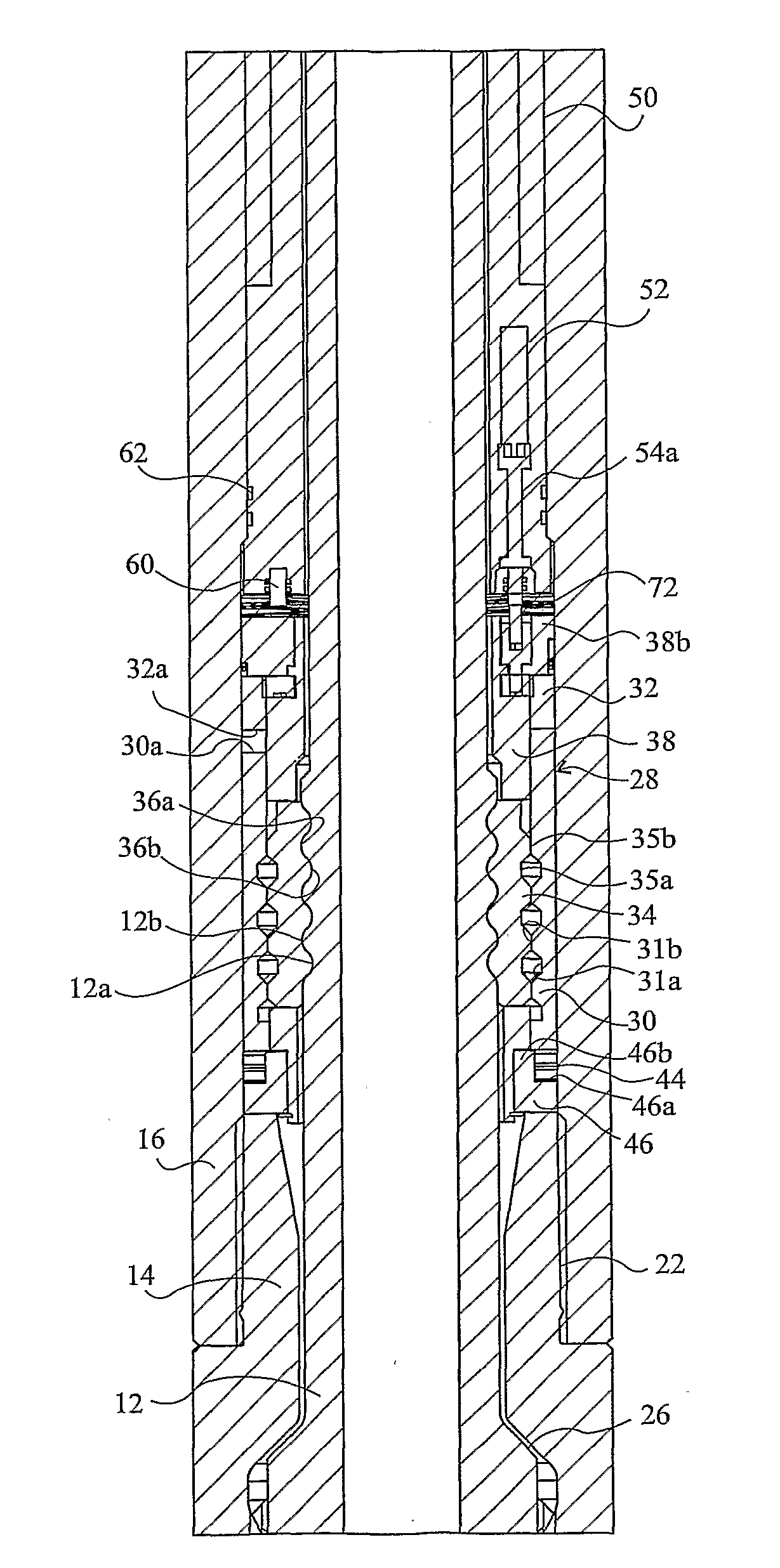
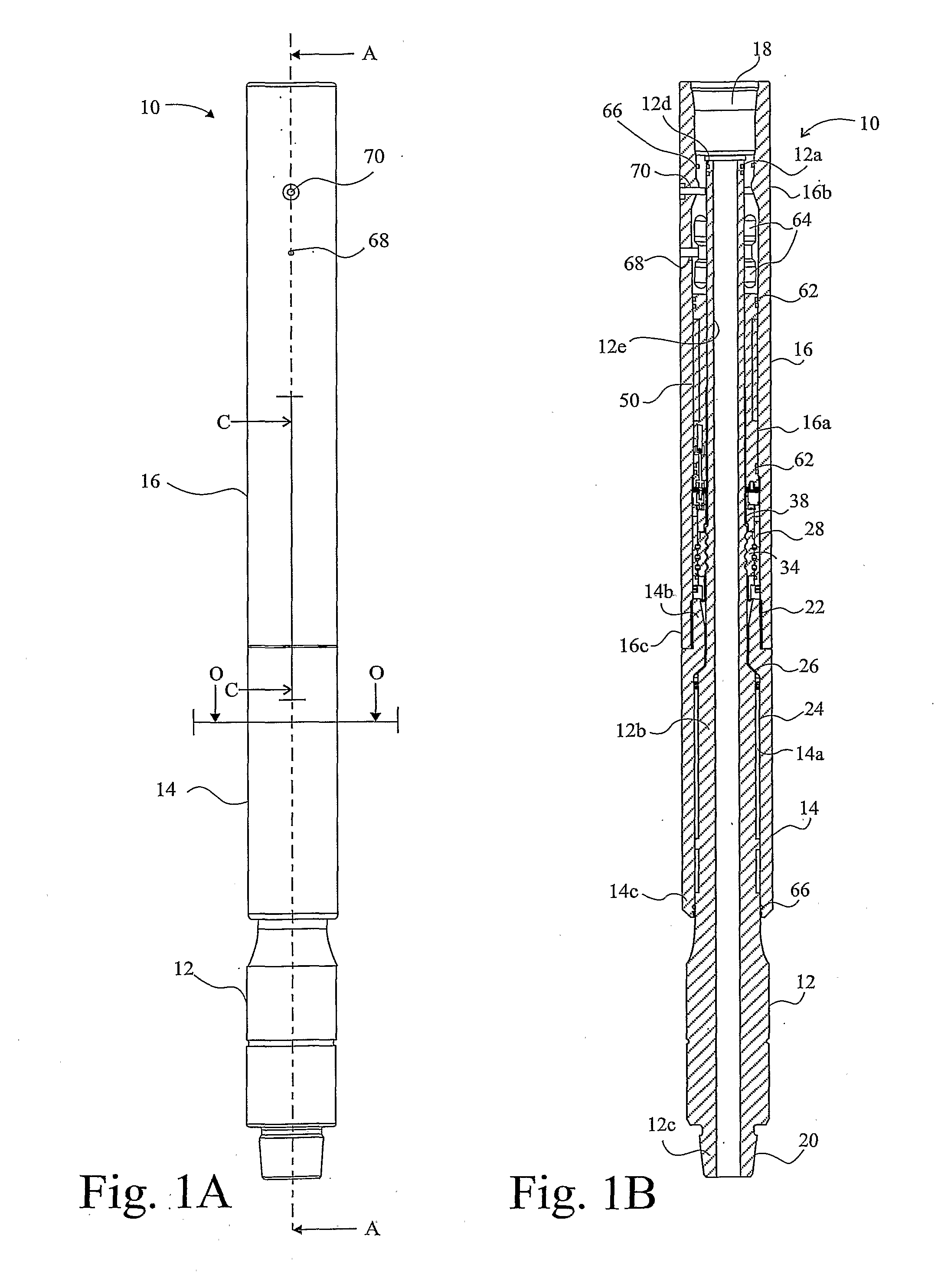
[0077]A disconnect device 10 in accordance with the present invention is shown in FIG. 1A. FIG. 1B shows a cross section of the device 10 of FIG. 1A along line A-A. With reference to FIGS. 1A and 1B, the device 10 is generally cylindrical and has a mandrel 12 that is located within a bore 14a of a spline housing 14 and a bore 16a of a trigger housing 16. The spline housing 14 surrounds a middle portion 12b of the mandrel 12 whilst the trigger housing 16 surrounds an upper portion 12a of the mandrel 12. An upper portion 14b of the spline housing 14 has a smaller diameter than the trigger housing 16 and is connected in a lower portion 16c of the trigger housing 16. The interface between the upper portion 14a of the spline housing 14 and the lower portion 16c of the trigger housing 16 forms a housing connection 22 that prevents axial movement therebetween.

[0078]A lower portion 12c of the mandrel 12 extends below the spline housing 14 and is shown exposed. The device 10 has a top connec...


PUM


Abstract

A downhole tool for incorporation in a drill pipe for selective operation of the tool from surface level when the tool is in a wellbore. The tool comprises a controller electrically powered by a power source separate from surface level, a first sensor of the controller to detect a dynamic variable of the tool in the wellbore and produce an output signal dependent thereon; a second sensor of the controller to detect a mechanical signal transmitted from an operator at surface level; a motor driven by the power source under the control of the controller when said mechanical signal is received; and an actuator driven by the motor to actuate the tool; wherein the controller switches between at least two states in response to changes in said dynamic variable, only in said second state the controller being receptive to said mechanical signal from the operator to drive the motor.

Description

[0001]This invention relates to disconnect and other devices for a downhole assembly or tool, and more specifically to a disconnect device that allows a controlled disconnect from a drilling bottom hole assembly. It also relates to such tools as circulating subs and other devices requiring a controlled movement to actuate them.BACKGROUND[0002]In the oil and gas industries, disconnect devices are typically used to separate a bottom hole assembly (BHA) from a drill string if, for example, the BHA becomes stuck. Once the drill string has been disconnected from the BHA, the operators can then attempt to recover the stuck BHA with a “fishing” tool. However, in situations where recovery of the BHA is impractical or impossible, the stuck BHA will be abandoned and drilling will recommence along a different route with a new BHA attached to the drill string.[0003]Typical methods for disconnecting a drill string from a stuck BHA involve dropping a dart, ball or mud slug of high density fluid f...

Claims


Application Information

Patent Timeline
Patent Type & Authority Applications(United States)
IPC IPC(8): E21B23/00
CPCE21B17/06
Inventor OLLERENSHAW, ANDYHUNTER, GORDON
Owner INTELLIGENT DRILLING TOOLS
Why Eureka
Try Eureka