Flexible shaft wind turbine

Inactive Publication Date: 2011-12-22
ENVISION ENERGY DENMARK
View PDF4 Cites 12 Cited by
  • Summary
  • Abstract
  • Description
  • Claims
  • Application Information

AI Technical Summary

Benefits of technology

[0009]It is an object of the invention to provide a wind turbine design having improv

Problems solved by technology

One of the disadvantages of such a system is that in order to compensate for vibrations and bending moments transferred through the hub shaft from the hub, the generator and the gearbox must be mounted on vibration damping elements which are coupled to the machine housing.
Such damping elements are subject to wear and tear during the lifetime of the system, often requiring replacement every 3-5 years in a r

Method used


Image

  • Flexible shaft wind turbine
  • Flexible shaft wind turbine
  • Flexible shaft wind turbine

Examples


Embodiment Construction

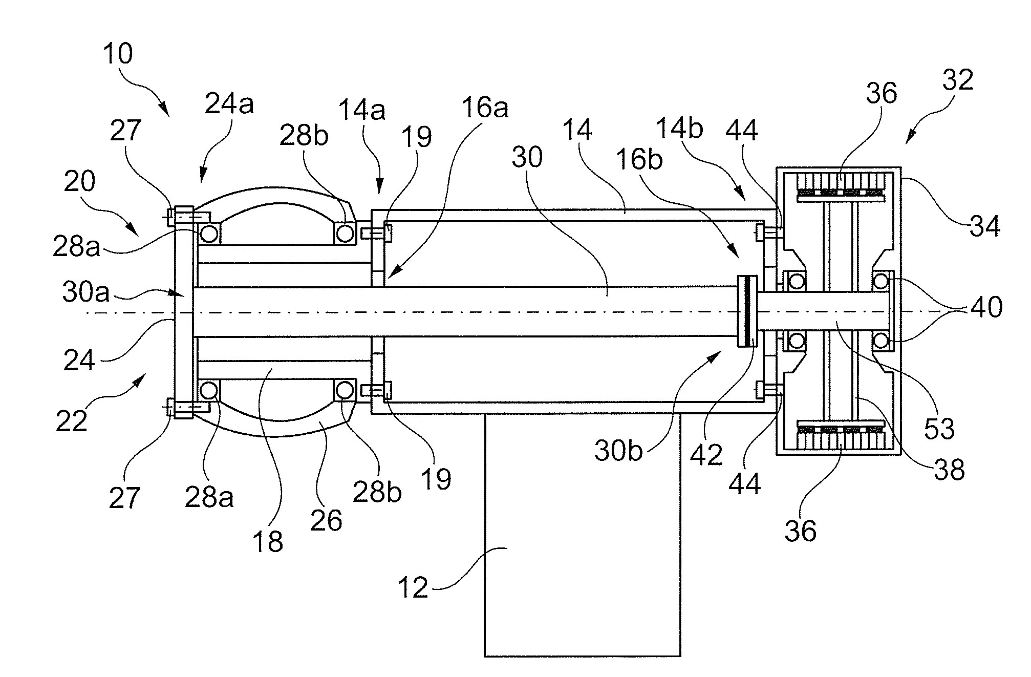
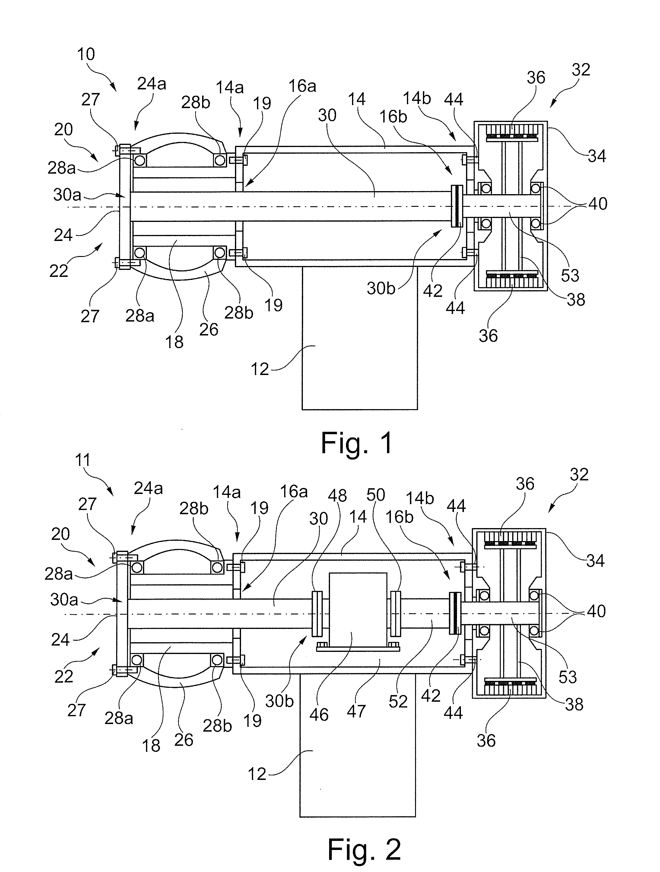
[0060]With reference to FIG. 1, a wind turbine according to a first embodiment of the invention is indicated generally at 10. The wind turbine 10 comprises a tower 12 and a turbine main frame 14, the main frame 14 provided at the upper end of the tower 12 having a windward side 14a and an opposed leeward side 14b. First and second through-going apertures 16a, 16b are defined in the windward side 14a and the opposed leeward side 14b respectively, the apertures 16a,16b in line with each other, to allow a shaft to extend through the main frame 14 from the windward side 14a to the leeward side 14b. The main frame 14 is adapted to swivel on top of the tower 12 to correct the yaw angle of the wind turbine 10, so that the turbine is continually facing the wind direction.

[0061]A support shaft 18 is provided at the windward side 14a of the main frame 14, rigidly mounted to the external surface of the main frame 14. The support shaft 18 comprises a cylindrical tubular body which is positioned...


PUM


Abstract

A horizontal-axis wind turbine of a rotor-support design is provided in which the structural load of the wind turbine rotor is carried by the wind turbine tower itself. The turbine uses a composite shaft to transfer torque from the wind turbine rotor to the generator, the shaft having high torsional strength but being flexible in bending. This prevents the transmission of bending moments from the rotor hub to the generator system. Accordingly, the components of the turbine can be rigidly mounted to the turbine main frame, removing the need for vibration damping elements. The result is a wind turbine of reduced weight, which can be modeled and designed for improved efficiency and performance. Furthermore, as the turbine components do not have to be load-balanced, the turbine can be of a modular construction for relatively easy servicing and/or upgrading.

Description

BACKGROUND OF THE INVENTION[0001]1. Field of the Invention[0002]The present invention relates to a wind turbine, in particular to a wind turbine having the wind turbine hub supported directly by the main frame, such that the transmission of torque from the hub to the generator is separated from the support of the rotor.[0003]2. Description of Related Art[0004]Rotor support-type wind turbines are a known alternative wind turbine design, wherein the structural load of the hub and rotor blades is provided by a fixed support shaft provided on the wind turbine main frame. As the hub is allowed to rotate freely about the support shaft, consequentially the structural load is transferred to the main frame while the torque provided by the spinning rotor blades is transferred to the generation system.[0005]U.S. Pat. No. 4,757,211 discloses a rotor support-type wind turbine wherein a rotor hub is mounted onto a cylindrical section of the machine housing, the structural load of the rotor hub be...

Claims


Application Information

Patent Timeline
IPC IPC(8): F03D11/02
CPCF03D11/0008F03D11/02F05B2240/14F05B2240/62Y02E10/722F05B2280/6003F05C2253/04F16C3/026Y02E10/721F05B2260/96F03D80/70F03D15/00F16C2360/31F03D15/20F03D80/30Y02E10/72F03D80/88F05B2240/50
Inventor REBSDORF, ANDERS VARMING
Owner ENVISION ENERGY DENMARK
Why Eureka
Try Eureka