Metal foil for secondary battery and secondary battery

a secondary battery and metal foil technology, applied in cell components, manufacturing tools, transportation and packaging, etc., can solve the problems of reducing the aperture ratio, reducing the strength, and requiring the removal of cutting chips, so as to suppress the short circuit and increase the aperture ratio.

Inactive Publication Date: 2011-12-22
FINECS
View PDF1 Cites 16 Cited by
  • Summary
  • Abstract
  • Description
  • Claims
  • Application Information

AI Technical Summary

Benefits of technology

[0012]Therefore, it is an object of the invention to provide a metal foil for secondary battery generating less cutting chips at the time of forming an opening and allowed to have a higher aperture ratio without reducing strength, and a secondary battery in which short circuit caused by generation of electrode debris can be suppressed.
[0019]According to the metal foil for secondary battery of the present invention, a small amount of cutting chips is generated when an opening is formed and it is possible to increase an aperture ratio without reducing strength.
[0020]According to the secondary battery of the present invention, it is possible to suppress a short circuit caused by generation of electrode debris.

Problems solved by technology

When the active material is applied to the front and back surfaces of the copper or aluminum metal foil, there is a disadvantage that the metal foil is less likely to be integrated with the active material and the active material is likely to fall off.
However, since cutting chips are generated in the method of forming through-holes by the rolling process, removal of the cutting chips is required.
Meanwhile, in the method of forming through-holes by the lath process, since strength against tension generated at the time of applying the active material is insufficient when the expansion rate is increased, it is not possible to increase the aperture ratio.

Method used


Image

  • Metal foil for secondary battery and secondary battery
  • Metal foil for secondary battery and secondary battery
  • Metal foil for secondary battery and secondary battery

Examples


first embodiment

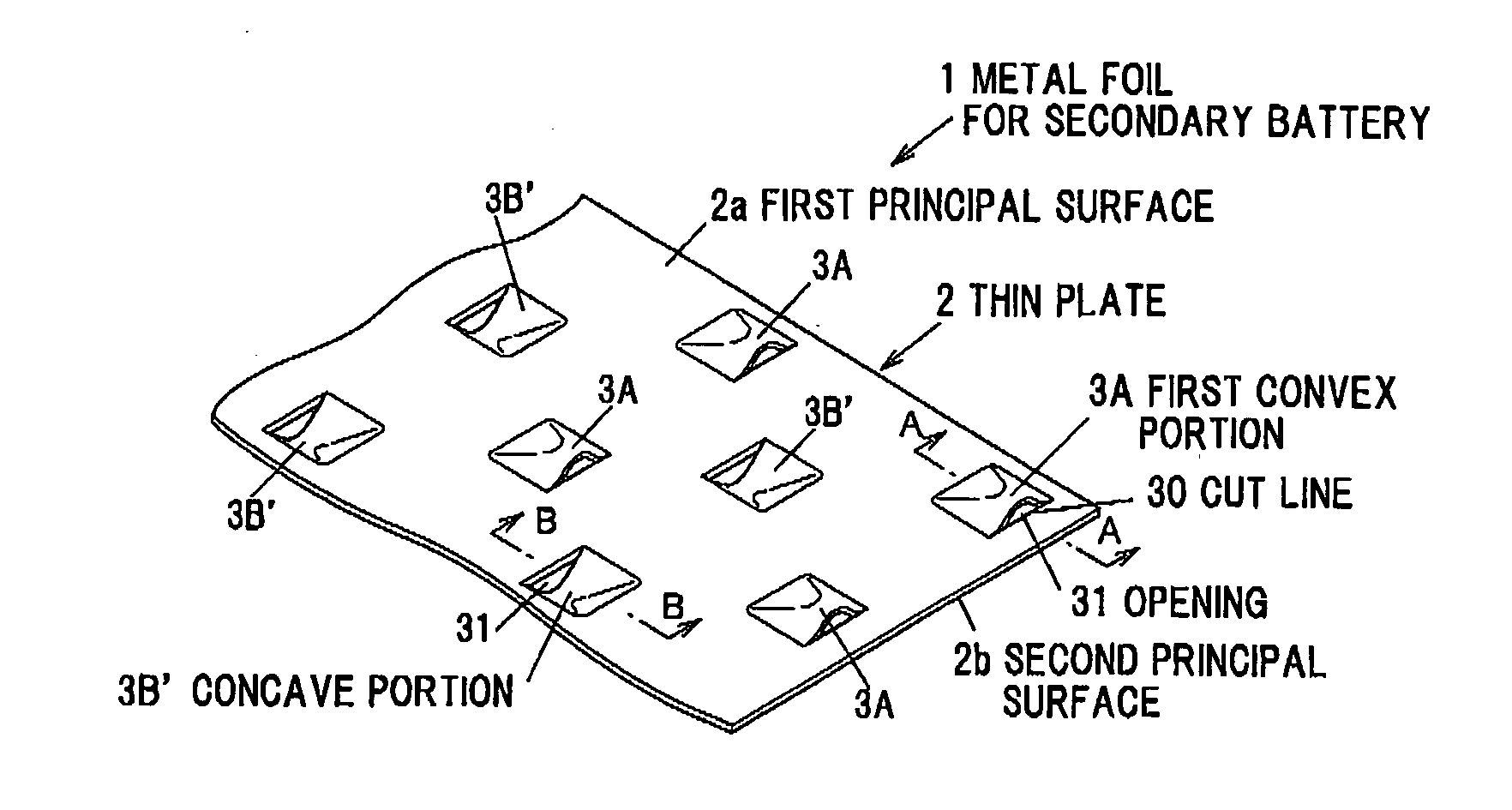
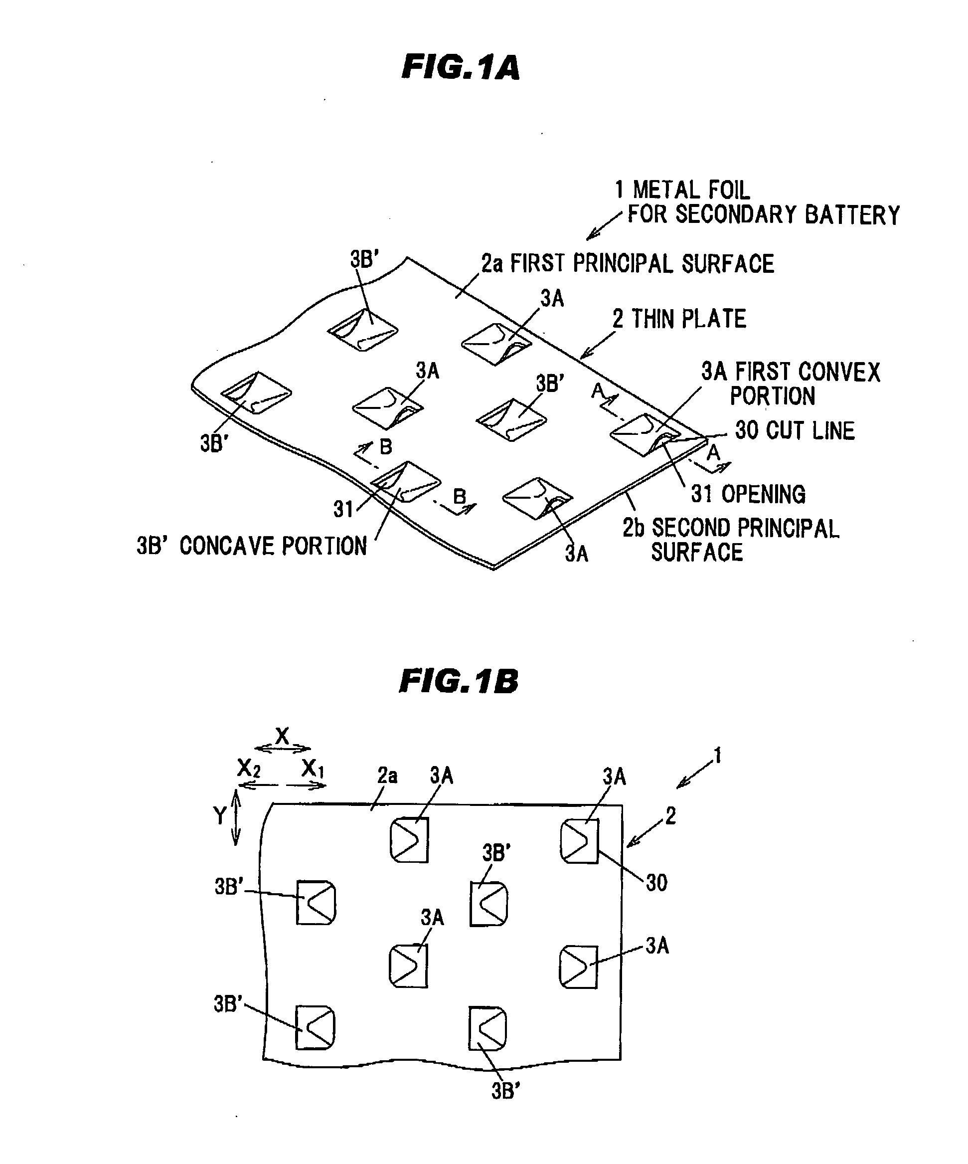
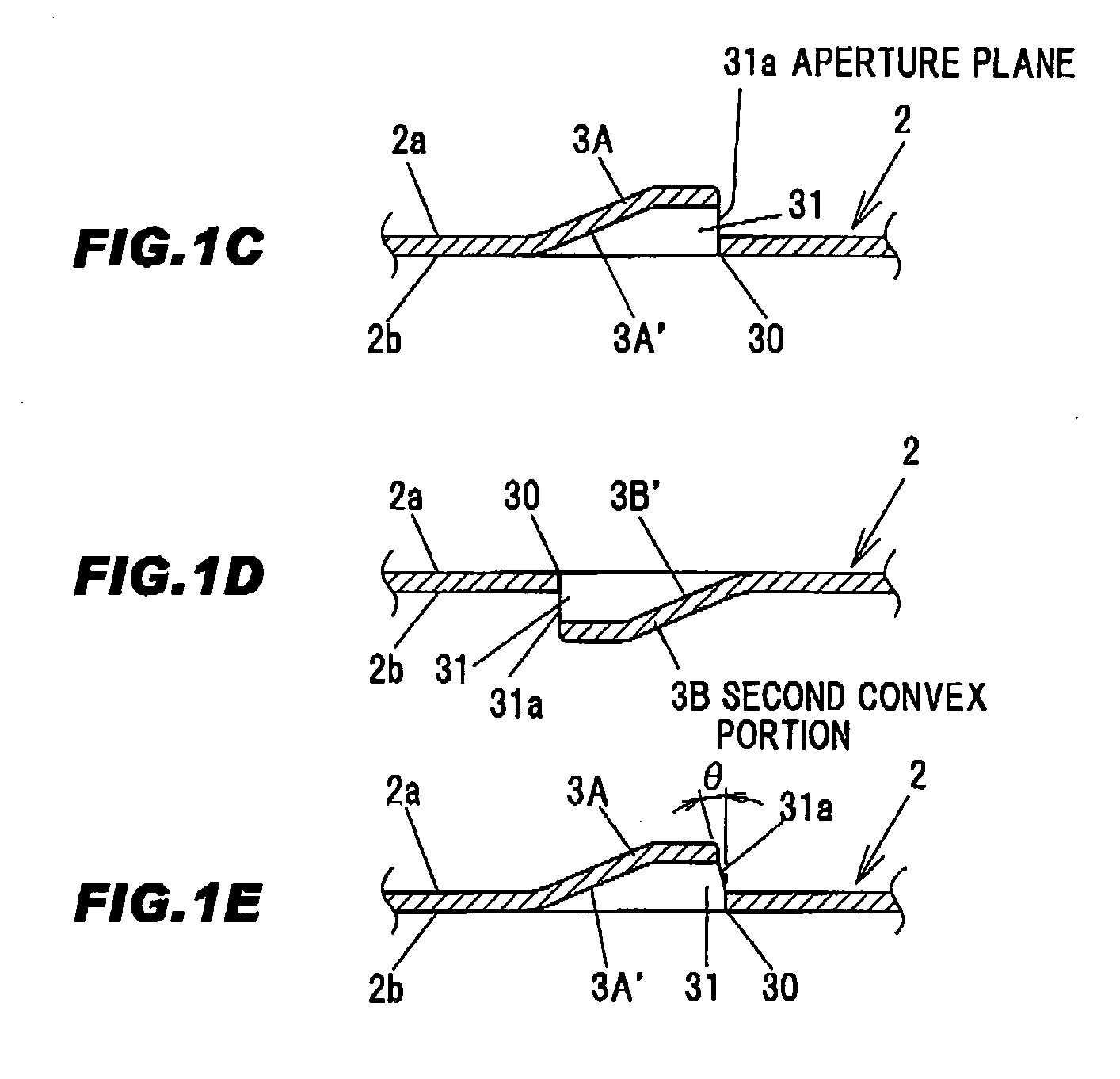
[0031]FIGS. 1A and 1B show a metal foil for secondary battery according to a first embodiment of the present invention, wherein FIG. 1A is a perspective view of a principal part and FIG. 1B is a plan view thereof. FIG. 1C is a cross sectional view taken on line A-A of FIG. 1A, FIG. 1D is a cross sectional view taken on line B-B of FIG. 1A and FIG. 1E is a cross sectional view showing a modification of FIG. 1C.

[0032]A metal foil 1 for secondary battery is provided with a metal thin plate 2 and plural first and second convex portions 3A and 3B respectively integrally formed on a first principal surface 2a of the thin plate 2 and on a second principal surface 2b opposite to the first principal surface 2a. Alternatively, the convex portion may be formed only on one principal surface.

[0033]The thin plate 2 is formed of metal such as, e.g., aluminum, copper, nickel, an alloy thereof or nickel-plated steel plate. In addition , the thin plate 2 has a thickness of, e.g., 20-100 μm. A planar ...

second embodiment

[0047]FIGS. 2A and 2B show a metal foil for secondary battery according to a second embodiment of the present invention, wherein FIG. 2A is a perspective view of a principal part and FIG. 2B is a plan view thereof. FIG. 2C is a cross sectional view taken on line C-C of FIG. 2A and FIG. 2D is a cross sectional view taken on line D-D of FIG. 2A.

[0048]The present embodiment is configured in the same manner as the first embodiment except that the opening 31 of the second convex portion 3B formed on the second principal surface 2b is opened in the same direction as the opening 31 of the first convex portion 3A formed on the first principal surface 2a. The manufacturing in the second embodiment can be carried out in the same manner as the first embodiment, and the second embodiment achieves the same effect as the first embodiment.

third embodiment

[0049]FIG. 3 is a perspective view of a principal part of a metal foil for secondary battery according to a third embodiment of the present invention. The present embodiment is configured in the same manner as the first embodiment except that the convex portions are arranged in a grid pattern (matrix pattern) in a row direction X as well as a column direction Y.

[0050]Plural first convex portions 3A are formed in a staggered manner on the first principal surface 2a of the thin plate 2 and plural convex portions 3B are arranged in a staggered manner on the second principal surface 2b so as to be located between the first convex portions 3A, thereby arranging the convex portions 3A and 3B in a grid pattern (matrix pattern) in the row direction X as well as the column direction Y. The opening 31 of the convex portion 3A is opened toward a direction X1 which is one of row directions X, and the opening 31 of the convex portion 3B is opened toward a direction X2 which is another row direct...


PUM

PropertyMeasurementUnit
inclination angleaaaaaaaaaa
timeaaaaaaaaaa
swellingaaaaaaaaaa

Abstract

A metal foil for secondary battery generating less cutting chips at the time of forming an opening and allowed to have a higher aperture ratio without reducing strength and a secondary battery in which short circuit caused by generation of electrode debris can be suppressed are provided. A metal foil 1 for secondary battery is provided with a metal thin plate 2, plural first convex portions 3A formed on a first principal surface 2a of the thin plate 2 by plastic forming and plural second convex portions 3B formed on a second principal surface 2b opposite to the first principal surface 2a by the plastic forming, wherein the convex portions 3A and 3B each have an opening 31 of which aperture plane 31a is orthogonal or substantially orthogonal to the principal surfaces 2a and the 2b.

Description

[0001]The present application is based on Japanese Patent Application No.2010-138271 filed on Jun. 17, 2010, the entire contents of which are incorporated herein by reference.BACKGROUND OF THE INVENTION[0002]1. Field of the Invention[0003]The invention relates to a metal foil for secondary battery and a secondary battery.[0004]2. Description of the Related Art[0005]In recent years, along with the popularization of portable devices such as a cell phone or a laptop computer and along with the development and practical application of an electric vehicle or a hybrid car, demand of a compact high-capacity battery has been increasing. Especially a lithium-ion battery has been used in various fields due to its lightweight and high energy density.[0006]The lithium-ion battery is basically composed of a cathode, an anode, a separator for insulating the cathode from the anode, and an electrolyte which permits ion movement between the cathode and the anode.[0007]In general, a metal foil formed...

Claims


Application Information

Patent Timeline
Patent Type & Authority Applications(United States)
IPC IPC(8): H01M4/72B32B3/10
CPCH01M4/742Y10T428/12361H01M4/78Y02E60/10
Inventor MATSUDA, NOBORUFURUKI, HIROSHIMATSUNAGA, HIDEYA
Owner FINECS
Why Eureka
Try Eureka