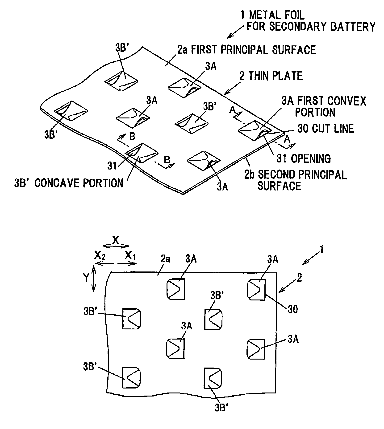
Metal foil for secondary battery and secondary battery
a secondary battery and metal foil technology, applied in cell components, manufacturing tools, transportation and packaging, etc., can solve the problems of reducing the aperture ratio, reducing the strength, and requiring the removal of cutting chips, so as to suppress the short circuit and increase the aperture ratio.
- Summary
- Abstract
- Description
- Claims
- Application Information
AI Technical Summary
Benefits of technology
Problems solved by technology
Method used
Image
Examples
first embodiment
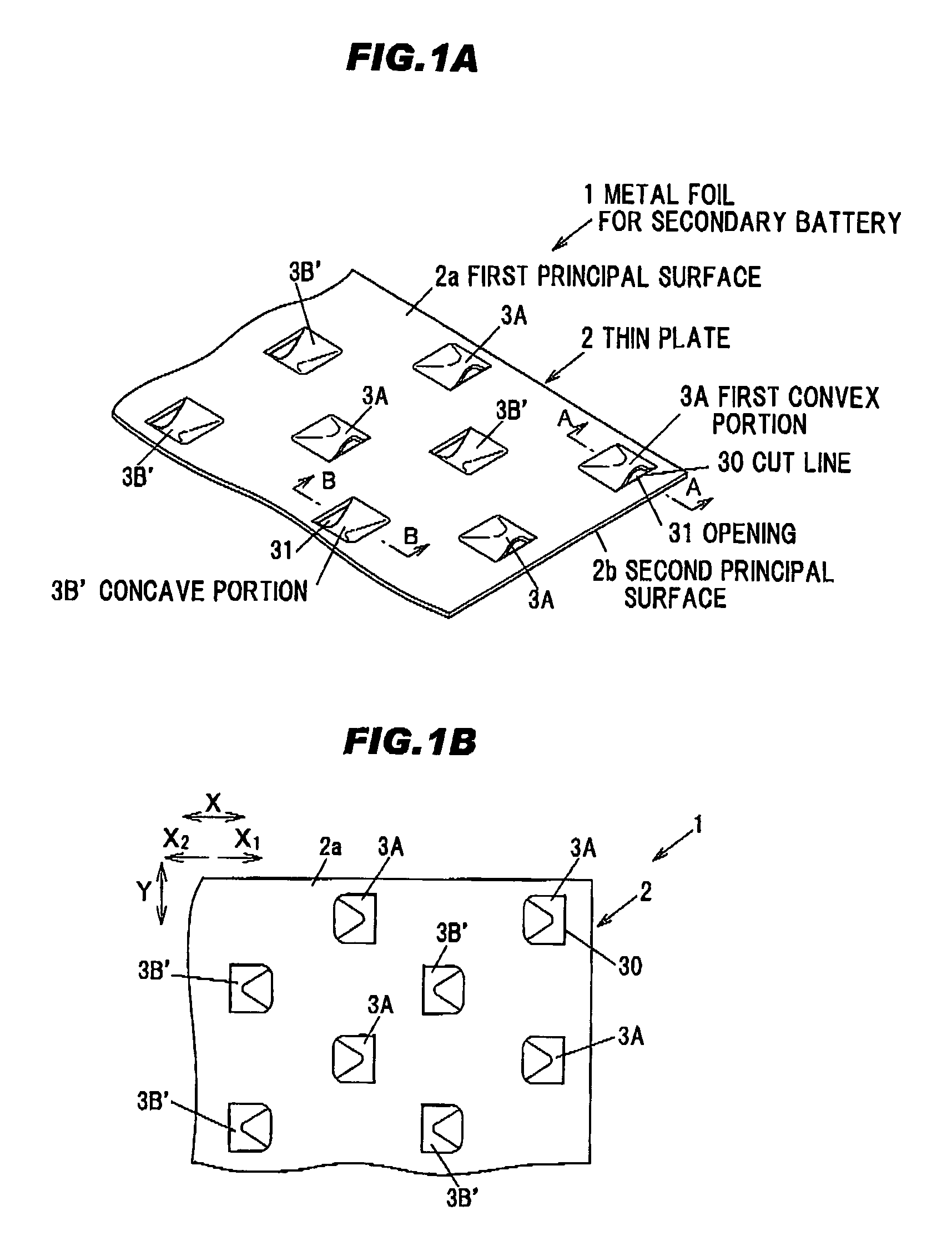
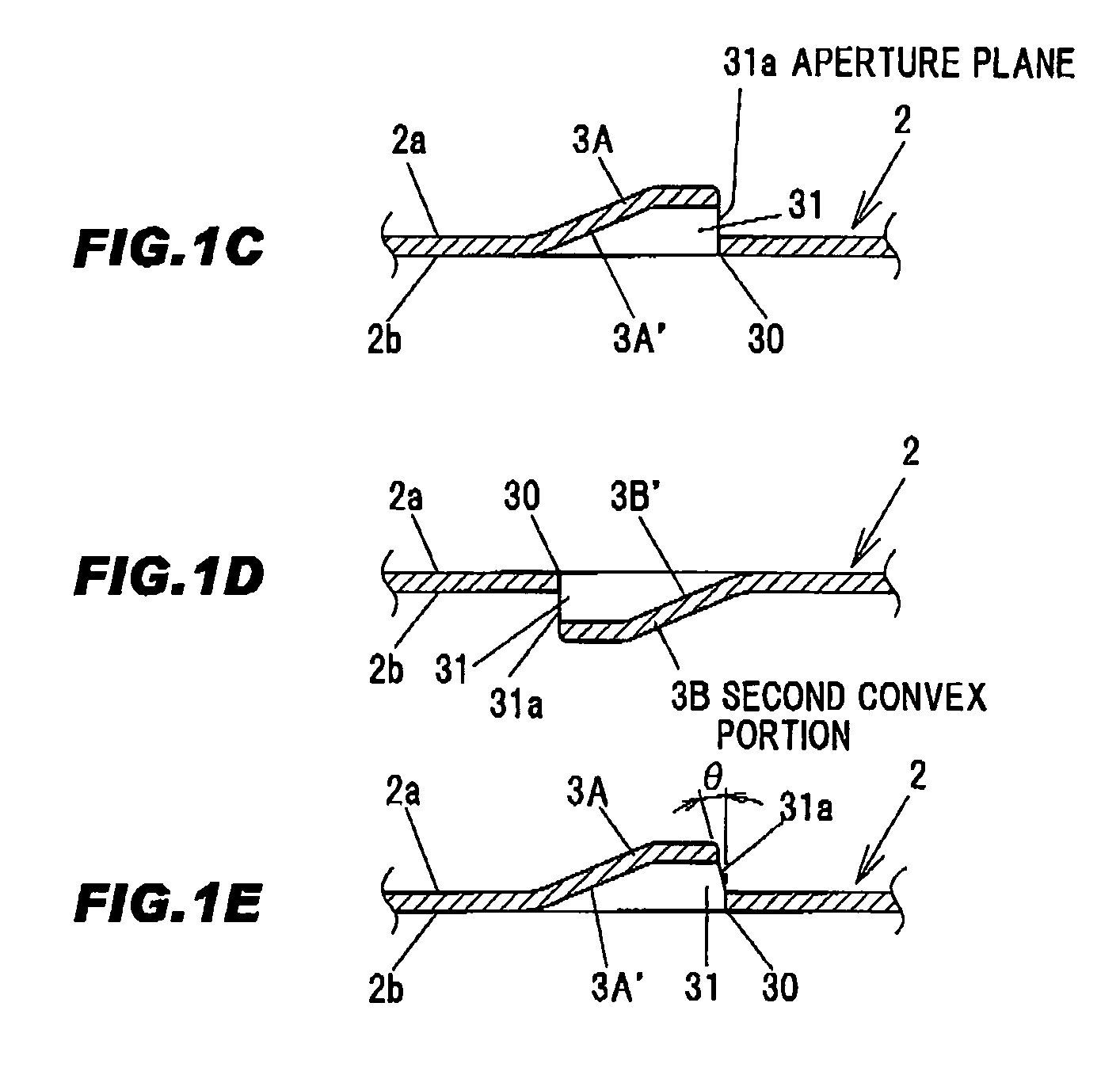
[0031]FIGS. 1A and 1B show a metal foil for secondary battery according to a first embodiment of the present invention, wherein FIG. 1A is a perspective view of a principal part and FIG. 1B is a plan view thereof. FIG. 1C is a cross sectional view taken on line A-A of FIG. 1A, FIG. 1D is a cross sectional view taken on line B-B of FIG. 1A and FIG. 1E is a cross sectional view showing a modification of FIG. 1C.
[0032]A metal foil 1 for secondary battery is provided with a metal thin plate 2 and plural first and second convex portions 3A and 3B respectively integrally formed on a first principal surface 2a of the thin plate 2 and on a second principal surface 2b opposite to the first principal surface 2a. Alternatively, the convex portion may be formed only on one principal surface.
[0033]The thin plate 2 is formed of metal such as, e.g., aluminum, copper, nickel, an alloy thereof or nickel-plated steel plate. In addition , the thin plate 2 has a thickness of, e.g., 20-100 μm. A planar ...
second embodiment
[0046]FIGS. 2A and 2B show a metal foil for secondary battery according to a second embodiment of the present invention, wherein FIG. 2A is a perspective view of a principal part and FIG. 2B is a plan view thereof. FIG. 2C is a cross sectional view taken on line C-C of FIG. 2A and FIG. 2D is a cross sectional view taken on line D-D of FIG. 2A.
[0047]The present embodiment is configured in the same manner as the first embodiment except that the opening 31 of the second convex portion 3B formed on the second principal surface 2b is opened in the same direction as the opening 31 of the first convex portion 3A formed on the first principal surface 2a. The manufacturing in the second embodiment can be carried out in the same manner as the first embodiment, and the second embodiment achieves the same effect as the first embodiment.
third embodiment
[0048]FIG. 3 is a perspective view of a principal part of a metal foil for secondary battery according to a third embodiment of the present invention. The present embodiment is configured in the same manner as the first embodiment except that the convex portions are arranged in a grid pattern (matrix pattern) in a row direction X as well as a column direction Y.
[0049]Plural first convex portions 3A are formed in a staggered manner on the first principal surface 2a of the thin plate 2 and plural convex portions 3B are arranged in a staggered manner on the second principal surface 2b so as to be located between the first convex portions 3A, thereby arranging the convex portions 3A and 3B in a grid pattern (matrix pattern) in the row direction X as well as the column direction Y. The opening 31 of the convex portion 3A is opened toward a direction X1 which is one of row directions X, and the opening 31 of the convex portion 3B is opened toward a direction X2 which is another row direct...
PUM
| Property | Measurement | Unit |
|---|---|---|
| inclination angle | aaaaa | aaaaa |
| time | aaaaa | aaaaa |
| swelling | aaaaa | aaaaa |
Abstract
Description
Claims
Application Information
 - R&D
- Intellectual Property
- Life Sciences
- Materials
- Tech Scout
- Unparalleled Data Quality
- Higher Quality Content
- 60% Fewer Hallucinations
Browse by: Latest US Patents, China's latest patents, Technical Efficacy Thesaurus, Application Domain, Technology Topic, Popular Technical Reports.
© 2025 PatSnap. All rights reserved.Legal|Privacy policy|Modern Slavery Act Transparency Statement|Sitemap|About US| Contact US: help@patsnap.com


