Eureka AIR delivers breakthrough ideas for toughest innovation challenges, trusted by R&D personnel around the world.

Microfluidic device with conductivity sensor

Inactive Publication Date: 2011-12-22
GENEASYS
View PDF6 Cites 0 Cited by
  • Summary
  • Abstract
  • Description
  • Claims
  • Application Information

AI Technical Summary

Benefits of technology

[0092]The mass-producible and inexpensive microfluidic device processes and / or analyses fluids, with aspects of the functioning of the microfluidic device related to fluidic flow rates being monitored and optimally controlled via the easily manufacturable hot-wire flow sensor.
[0119]The mass-producible and inexpensive microfluidic device processes and / or analyses fluids, with aspects of the functioning of the microfluidic device related to presence or absence of fluids in a given location being monitored and optimally controlled via the easily manufacturable liquid sensor.
[0146]The mass-producible and inexpensive microfluidic device processes and / or analyses fluids, with aspects of the functioning of the microfluidic device related to fluidic flow rates being monitored and optimally controlled via the easily manufacturable capillary meniscus marching velocity sensor.
[0173]The mass-producible and inexpensive microfluidic device processes and / or analyses fluids, with aspects of the functioning of the microfluidic device related to conductivity of liquid mixtures being monitored and optimally controlled via the easily manufacturable conductivity sensor.

Problems solved by technology

Insufficient stringency can result in a high degree of nonspecific binding.
Excessive stringency can lead to a failure of appropriate binding, which results in diminished sensitivity.
Despite the advantages that molecular diagnostic tests offer, the growth of this type of testing in the clinical laboratory has been slower than expected and remains a minor part of the practice of laboratory medicine.
This is primarily due to the complexity and costs associated with nucleic acid testing compared with tests based on methods not involving nucleic acids.
However, controlling fluid flow through the LOC device, adding reagents, controlling reaction conditions and so on necessitate bulky external plumbing and electronics.
Connecting a LOC device to these external devices effectively restricts the use of LOC devices for molecular diagnostics to the laboratory setting.
The cost of the external equipment and complexity of its operation precludes LOC-based molecular diagnostics as a practical option for point-of-care settings.

Method used


Image

  • Microfluidic device with conductivity sensor
  • Microfluidic device with conductivity sensor
  • Microfluidic device with conductivity sensor

Examples


Embodiment Construction

Overview

[0300]This overview identifies the main components of a molecular diagnostic system that incorporates embodiments of the present invention. Comprehensive details of the system architecture and operation are set out later in the specification.

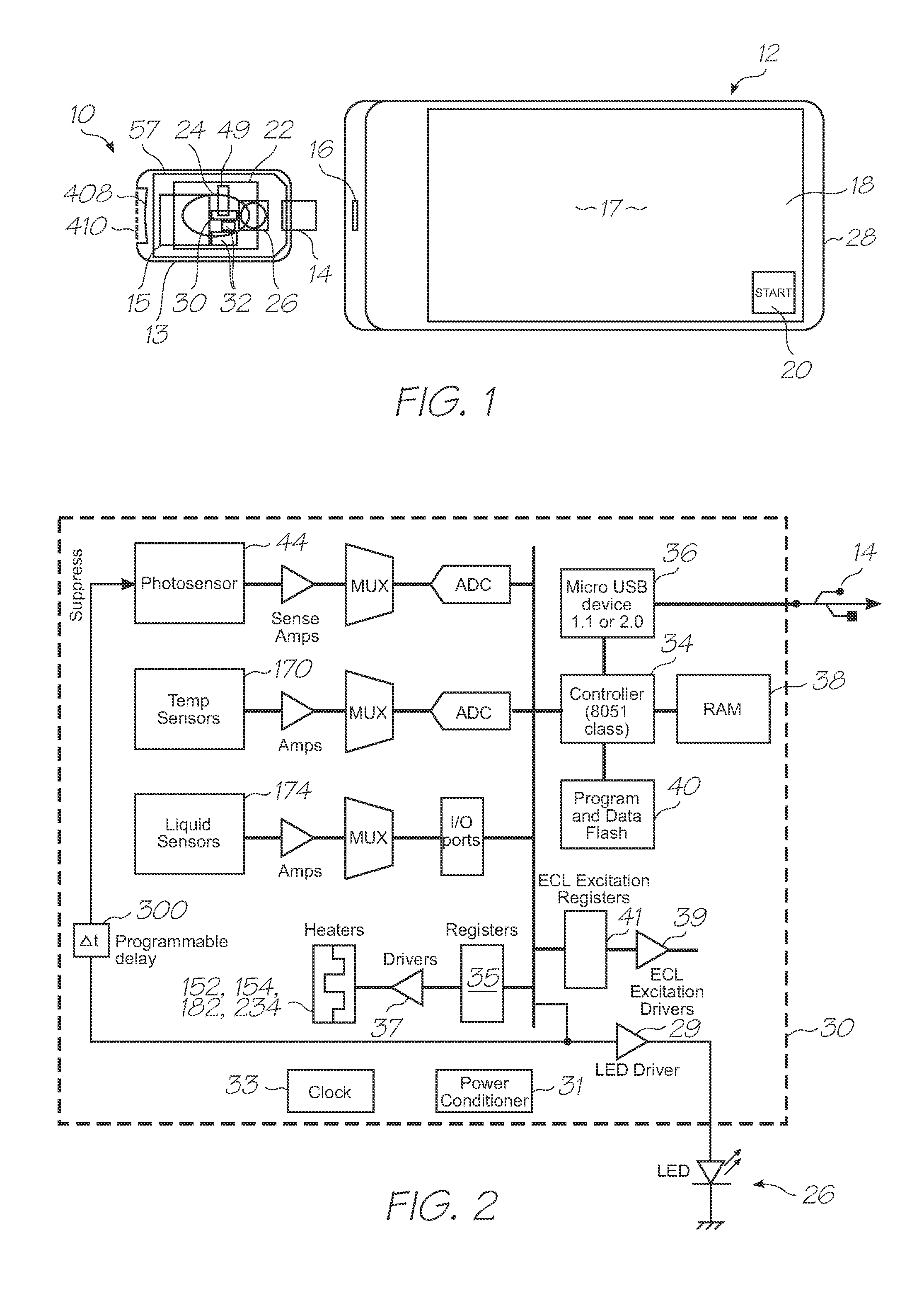
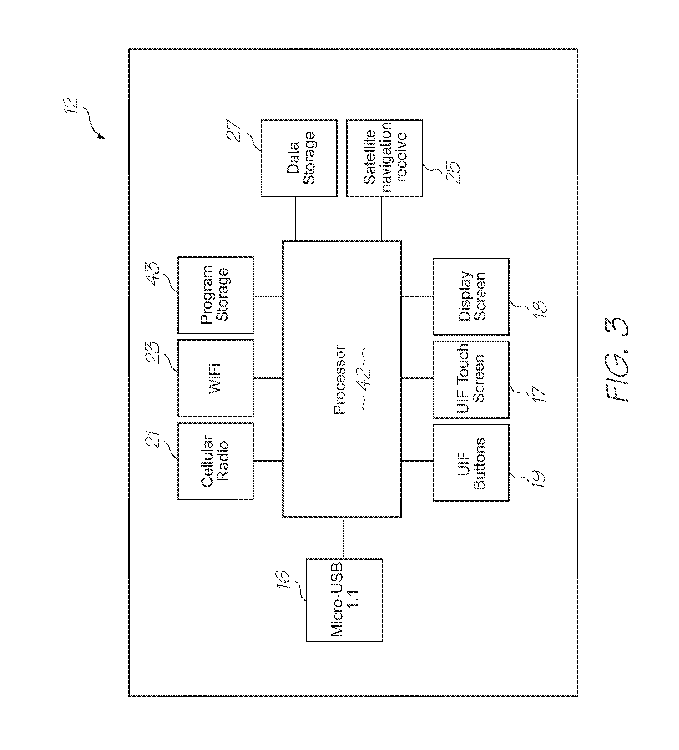
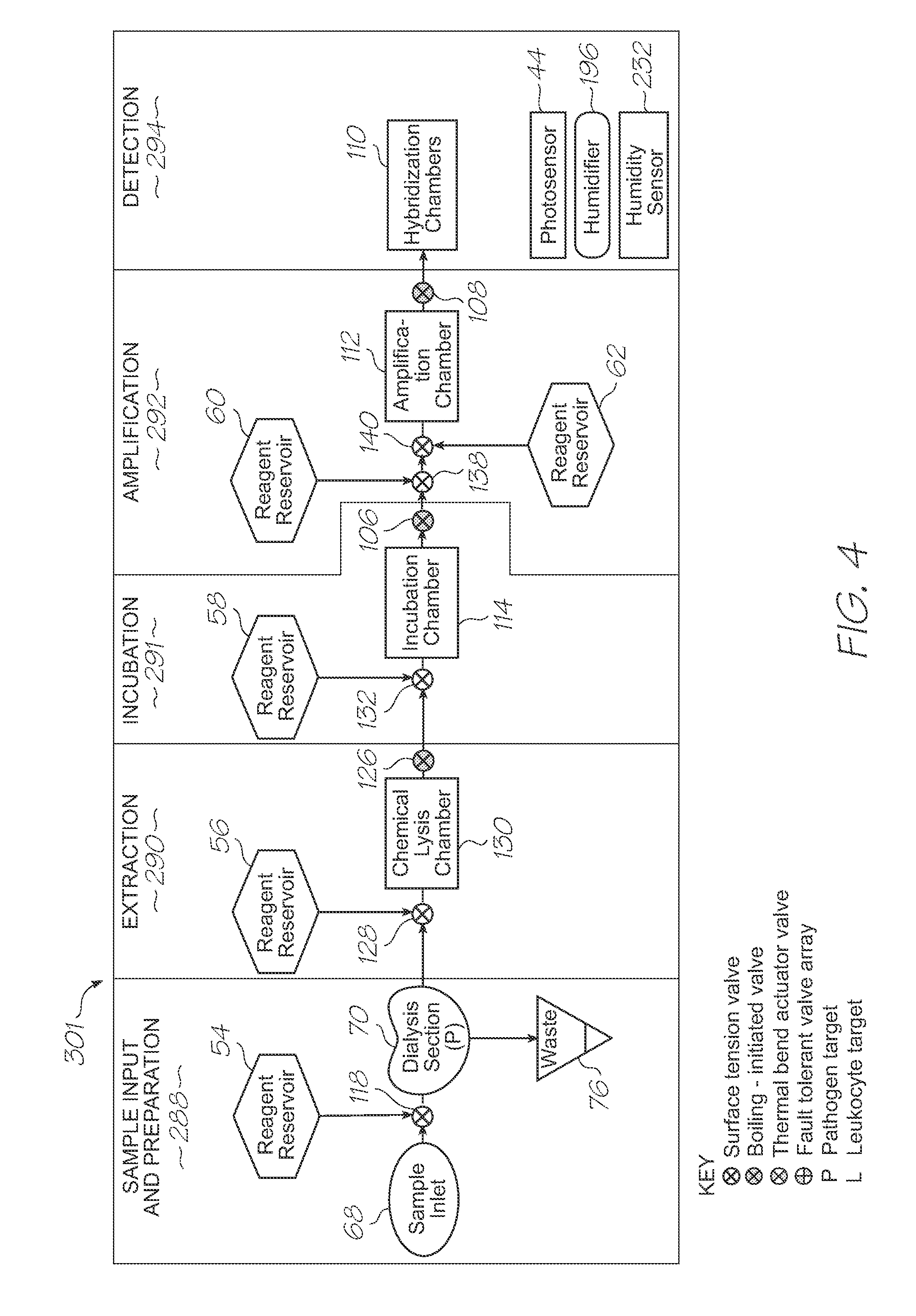
[0301]Referring to FIGS. 1, 2, 3, 120 and 121, the system has the following top level components:

[0302]Test modules 10 and 11 are the size of a typical USB memory key and very cheap to produce. Test modules 10 and 11 each contain a microfluidic device, typically in the form of a lab-on-a-chip (LOC) device 30 preloaded with reagents and typically more than 1000 probes for the molecular diagnostic assay (see FIGS. 1 and 120). Test module 10 schematically shown in FIG. 1 uses a fluorescence-based detection technique to identify target molecules, while test module 11 in FIG. 120 uses an electrochemiluminescence-based detection technique. The LOC device 30 has an integrated photosensor 44 for fluorescence or electrochemiluminescence detection...


PUM

PropertyMeasurementUnit
Areaaaaaaaaaaa
Temperatureaaaaaaaaaa
Electrical resistanceaaaaaaaaaa

Abstract

A microfluidic device for processing a fluid, the microfluidic device having an inlet for receiving the fluid, functional sections for processing the fluid, a flow-path extending from the inlet into at least some of the functional sections, CMOS circuitry for operative control of the functional sections, and, a conductivity sensor with a first terminal and a second terminal spaced apart along the flow-path, and a first electrode and a second electrode positioned between the first terminal and the second terminal and spaced apart along the flow-path, wherein, the CMOS circuitry is configured to generate a current between the first terminal and the second terminal, and measure a voltage across the first electrode and the second electrode such that conductivity of the fluid in the flow-path is derived from the current and the measured voltage.

Description

FIELD OF THE INVENTION[0001]The present invention relates to diagnostic devices that use microsystems technologies (MST). In particular, the invention relates to microfluidic and biochemical processing and analysis for molecular diagnostics.CO-PENDING APPLICATIONS[0002]The following applications have been filed by the Applicant which relate to the present application:GBS001USGBS002USGBS003USGBS005USGBS006USGSR001USGSR002USGAS001USGAS002USGAS003USGAS004USGAS006USGAS007USGAS008USGAS009USGAS010USGAS012USGAS013USGAS014USGAS015USGAS016USGAS017USGAS018USGAS019USGAS020USGAS021USGAS022USGAS023USGAS024USGAS025USGAS026USGAS027USGAS028USGAS030USGAS031USGAS032USGAS033USGAS034USGAS035USGAS036USGAS037USGAS038USGAS039USGAS040USGAS041USGAS042USGAS043USGAS044USGAS045USGAS046USGAS047USGAS048USGAS049USGAS050USGAS054USGAS055USGAS056USGAS057USGAS058USGAS059USGAS060USGAS061USGAS062USGAS063USGAS065USGAS066USGAS067USGAS068USGAS069USGAS070USGAS080USGAS081USGAS082USGAS083USGAS084USGAS085USGAS086USGAS087USGAS...

Claims


Application Information

Patent Timeline
IPC IPC(8): C40B40/06C12M1/38G01N27/00
CPCB01L3/5027Y10T436/25B01L3/502738B01L7/52B01L2200/10B01L2300/023B01L2300/024B01L2300/0636B01L2300/0654B01L2300/0883B01L2300/10B01L2300/1827B01L2400/0406B01L2400/0633B01L2400/0677B01L2400/0688F16K99/003F16K99/0036G01N27/223C12Q1/68Y10T436/107497Y10T436/173845Y10T436/143333Y10T436/11Y10T436/145555Y10T436/203332Y10T436/25375B01L3/502707Y10T137/0352Y10T137/0391Y10T137/1044Y10T137/206Y10T137/2076Y10T137/2202Y02A90/10
Inventor AZIMI, MEHDISILVERBROOK, KIA
Owner GENEASYS
Why Eureka
Eureka Blog
Learn More