Eureka AIR delivers breakthrough ideas for toughest innovation challenges, trusted by R&D personnel around the world.

Power supply

a power supply and battery technology, applied in the field of power supply, can solve the problems of battery capacity loss, energy consumption of passivation layer, and lithium battery type not being able to function as energy storage devices, and achieve the effect of reducing the need for maintenance and/or intervention

Inactive Publication Date: 2011-12-29
AB SKF
View PDF9 Cites 5 Cited by
  • Summary
  • Abstract
  • Description
  • Claims
  • Application Information

AI Technical Summary

Benefits of technology

[0005]In one example of a power supply according to the invention, the primary cell is a liquid cathode lithium cell, such as a lithium thionyl chloride battery having a lithium anode, a carbon cathode current collector and an electrolyte comprising a solution of lithium aluminium tetrachloride in thionyl chloride. Typically, the cell will also comprise a porous separator, e.g. a layer of non-woven fibreglass material, which physically and electrically isolates the lithium anode from the carbon cathode, but which allows the migration of ions via the electrolyte. During the manufacturing process, the battery is filled with the electrolyte solution and upon contact, the lithium anode reacts with the electrolyte and a passivation layer of aluminium chloride forms on the anode. Without the passivation layer, this type of lithium battery would not function as an energy storage device because the lithium would self-discharge and degrade quite rapidly. Thus, the passivation layer allows the battery to have a very low self discharge rate and a long shelf life.
[0007]Furthermore, as mentioned, the passivation layer minimises self discharge. It has been found that the rate of self-discharge increases in the absence or partial absence of a passivation layer, even when a continuous low current is drawn from the battery.
[0009]Preferably, the primary cell current is limited to a corresponding primary current density of 10 μA / cm2 or less. More preferably, the current limiter limits the current density to 5 μA / cm2 or less, to prevent any increase in the porosity of the passivation layer and prevent any significant leakage current from the battery once placed in a circuit. The effect of the present invention, therefore, is to minimise such leakage currents and to prevent loss of battery capacity through ‘self-repair’ of a damaged passivation layer. A power supply according to the invention can therefore continuously power a device for at least 20 years, preferably at least 25 or 30 years.
[0011]Voltage delay is not a problem in a power supply according to the invention, because the primary cell current is limited to a value at which the metal ions in the battery can pass through the passivation layer unhindered. Thus, a battery in a power supply according to the invention is discharged at a very low rate, which has the further advantage of preventing carbon pore blockage when the battery has a carbon cathode. During battery discharge at a rate that breaks the anode passivation layer, the broken-off pieces of the layer and other discharge products are deposited or precipitated in the carbon electrode pores, thereby blocking access to unused reaction sites and reducing battery capacity. This mechanism is also known as cathode passivation and is a common cause of premature depletion, particularly in lithium batteries. Limiting the primary cell current to a value that does not damage the passivation layer therefore has several benefits.
[0020]The invention allows a device to function using a primary cell battery in a particular mode so as to ensure that the device can run for an extended period of time without requiring battery replacement. This reduces the necessity for maintenance and / or intervention for the device.

Problems solved by technology

Without the passivation layer, this type of lithium battery would not function as an energy storage device because the lithium would self-discharge and degrade quite rapidly.
If the current density then falls to a lower level, the passivation layer starts to rebuild, but the rebuilding of the passivation layer requires energy and occurs at a loss of battery capacity.
The inventors believe that even a spike of current in excess of the primary current threshold value can damage the passivation layer to an extent that leads to a loss of battery capacity when the damage is repaired.

Method used


Image

  • Power supply
  • Power supply

Examples


Embodiment Construction

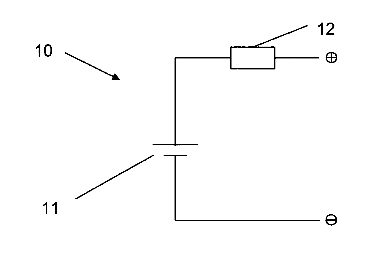
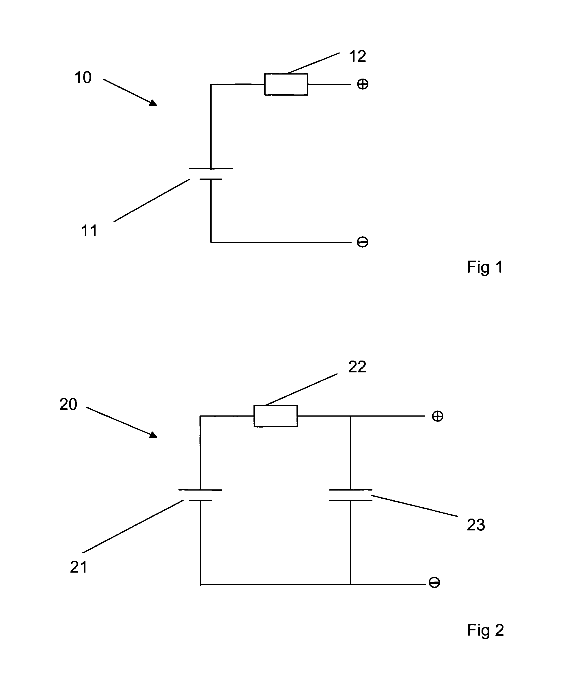
[0034]FIG. 1 illustrates an example of a power supply according to the present invention. The power supply 10 comprises a primary cell 11, which is a conventional battery of the type having an anode, a cathode current collector and an electrolyte. The primary cell 11 is further of the type which comprises a passivation layer on a surface of the anode, formed as a result of a chemical reaction between the anode and the electrolyte. In the example shown, the primary cell is a 3.6 V lithium thionyl chloride battery. Such batteries are particularly suitable for reliably providing power, preferably continuous power (particularly at low current levels), to a device for a long duration. Such batteries also have a long shelf life, due to the passivation layer, which layer largely prevents self discharge of the battery.

[0035]Although lithium batteries are often designated as long-life batteries, the inventors have found that when connected to a device such as e.g. a machine condition monitor...


PUM


Abstract

The present invention concerns a power supply (10) comprising a primary cell (11) adapted to provide a primary cell current. The primary cell (11) comprises an anode, a cathode current collector and an electrolyte, whereby a passivation layer is formed on a surface of the anode as a result of a chemical reaction between the anode and the electrolyte. To ensure that the passivation layer remains essentially intact for the lifetime of the primary cell, the power supply (10) further comprises a current limiter (12) that is configured to prevent the magnitude of the primary cell current exceeding a value that would damage the passivation layer.

Description

TECHNICAL FIELD[0001]This invention relates to a power supply comprising a primary cell, which is configured to deliver a continuous primary cell current for an extremely long duration. The invention is further directed to autonomous devices provided with the inventive power supply.BACKGROUND[0002]An autonomous device requiring a continuous and very low level of electrical power is generally provided with an internal electrical power source such as a battery, to supply the required power. Whilst the storage and discharge properties of the battery are selected to be appropriate for the device, such batteries do not always provide the anticipated amount of current or power before becoming depleted. This makes it difficult to ensure a reliable duration of the power source. Whilst the battery may be over-specified in an attempt to alleviate this, such a solution is not ideal and will not always resolve the problem.[0003]One of the aims of the present invention is to improve the reliabil...

Claims


Application Information

Patent Timeline
IPC IPC(8): H02J7/00
CPCH01M4/382H01M6/14H01M2200/108H01M16/00H01M6/5033
Inventor DE WIT, FRANKTATAR, FLORIN
Owner AB SKF
Why Eureka
Eureka Blog
Learn More