
Low input bias current chopping switch circuit and method

a chopping switch and low input bias current technology, applied in the direction of pulse automatic control, dc isolation amplifier, pulse technique, etc., can solve the problem of not much design flexibility for adjusting these two variables in order to meet certain design requirements, and the prior art chopper stabilization circuitry is associated with an increased input bias current and other problems, to achieve the effect of low output ripple noise and low input bias curren

Active Publication Date: 2011-12-29
TEXAS INSTR INC
View PDF0 Cites 7 Cited by
  • Summary
  • Abstract
  • Description
  • Claims
  • Application Information

AI Technical Summary

Benefits of technology

The present invention provides a chopper-stabilized circuit that has low output ripple noise and low input bias current. The circuit includes pre-chopping circuitry, main chopping circuitry, post-chopping circuitry, and output chopping circuitry. The chopping circuitry uses a first chopping frequency to chop an input signal and a second chopping frequency to produce a second chopped signal. The second chopped signal is then filtered using a switched capacitor notch filter to produce a filtered output signal. The filtered output signal is then combined with a second operational transconductance amplifier to produce an output signal. The invention provides a solution for reducing ripple noise in a chopper-stabilized circuit.

Problems solved by technology

However, a major drawback of the known prior art chopper stabilization circuitry is the associated increased input bias current.
Any mismatches in the chopping switches and / or associated parasitic elements cause a difference between the amount of injected charge that flows into and out of the two input terminals, respectively.
While the lowest possible chopping clock voltage level and smallest possible chopping switch size should always be used to minimize charge injection and clock feed-through, there is not much design flexibility for adjusting these two variables in order to meet certain design specifications, such as noise, speed, and signal level.
Lowering the chopping frequency reduces input bias current, but leads to the need for larger filter capacitors to maintain a similar level of chopping ripple (i.e., chopping-clock-induced ripple or “ripple noise”) at the amplifier output.
However, the improved design techniques used in modern chopper-stabilized operational amplifiers and auto-zero operational amplifiers result in trade-offs between input referred noise and quiescent supply current (Iq).
While auto-zeroing methods provide low ripple noise at the amplifier output, its in-band noise is high due to aliasing or noise folding.
On the other hand, chopper stabilization techniques present lower in-band noise due to absence of noise folding, but output ripple noise is relatively higher.
This creates large ripple voltages at the amplifier outputs.
Although basic auto-zero amplifiers do not shift their input offset to their auto-zero frequency like chopper-stabilized amplifiers, auto-zero amplifiers suffer from aliasing or folding back of their broadband noise spectrums during their zeroing cycles.
This increases the overall input referred noise of auto-zero amplifiers.
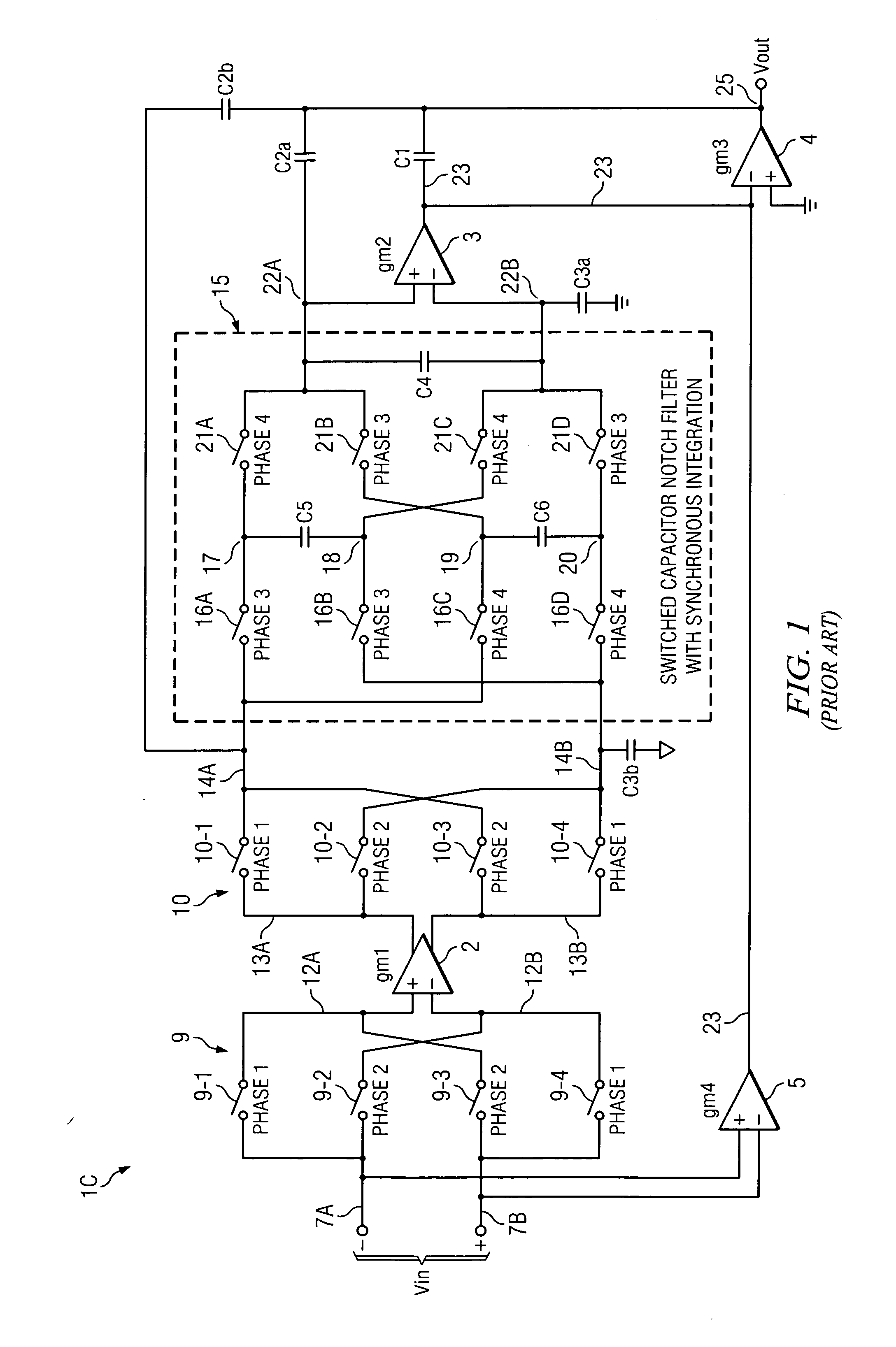
Unfortunately, the chopper-stabilized amplifier in Prior Art FIG. 1 generates residual error on its inputs 7A and 7B due to charge injection from the chopping signal, and this results in an increase in input bias current.
Although decreasing the chopping clock frequency reduces the input bias current, it also results in increased ripple voltage or requires an unacceptable increase in the size of the notch filter capacitors.
(Note that this would also be true for a continuous-time filter; that is, decreasing the chopping clock frequency would result in increased ripple voltage or would require an unacceptable increase in capacitances in the continuous-time filter.)
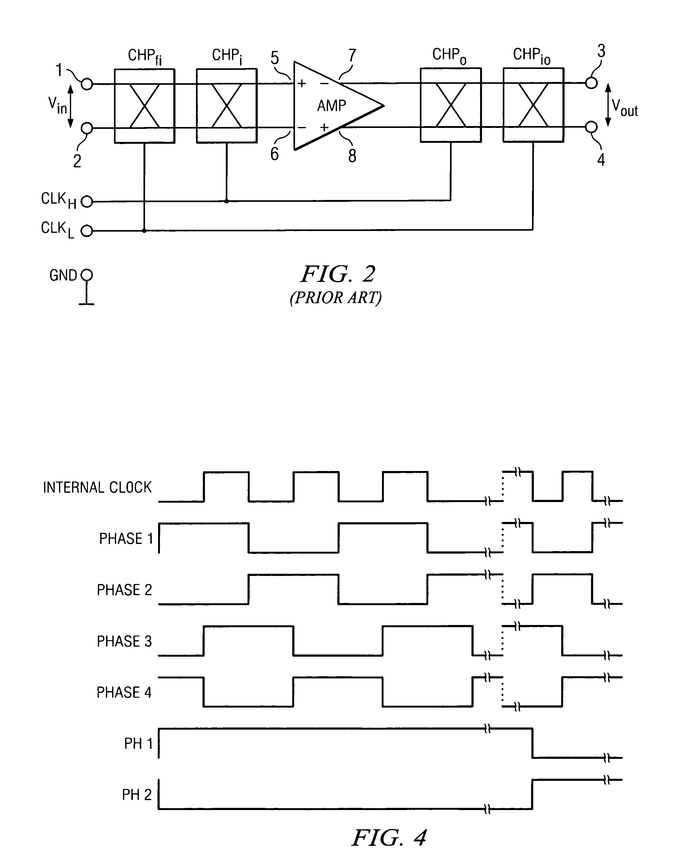
As a result, the DC offset cancellation is not optimal because charge injection of the switches in choppers CHPi and CHPo produces a DC offset.
However, this technique, referred to as “nested chopping”, increases parasitics on the output affecting input offset voltage performance.

Method used


Image

  • Low input bias current chopping switch circuit and method
  • Low input bias current chopping switch circuit and method
  • Low input bias current chopping switch circuit and method

Examples


Embodiment Construction

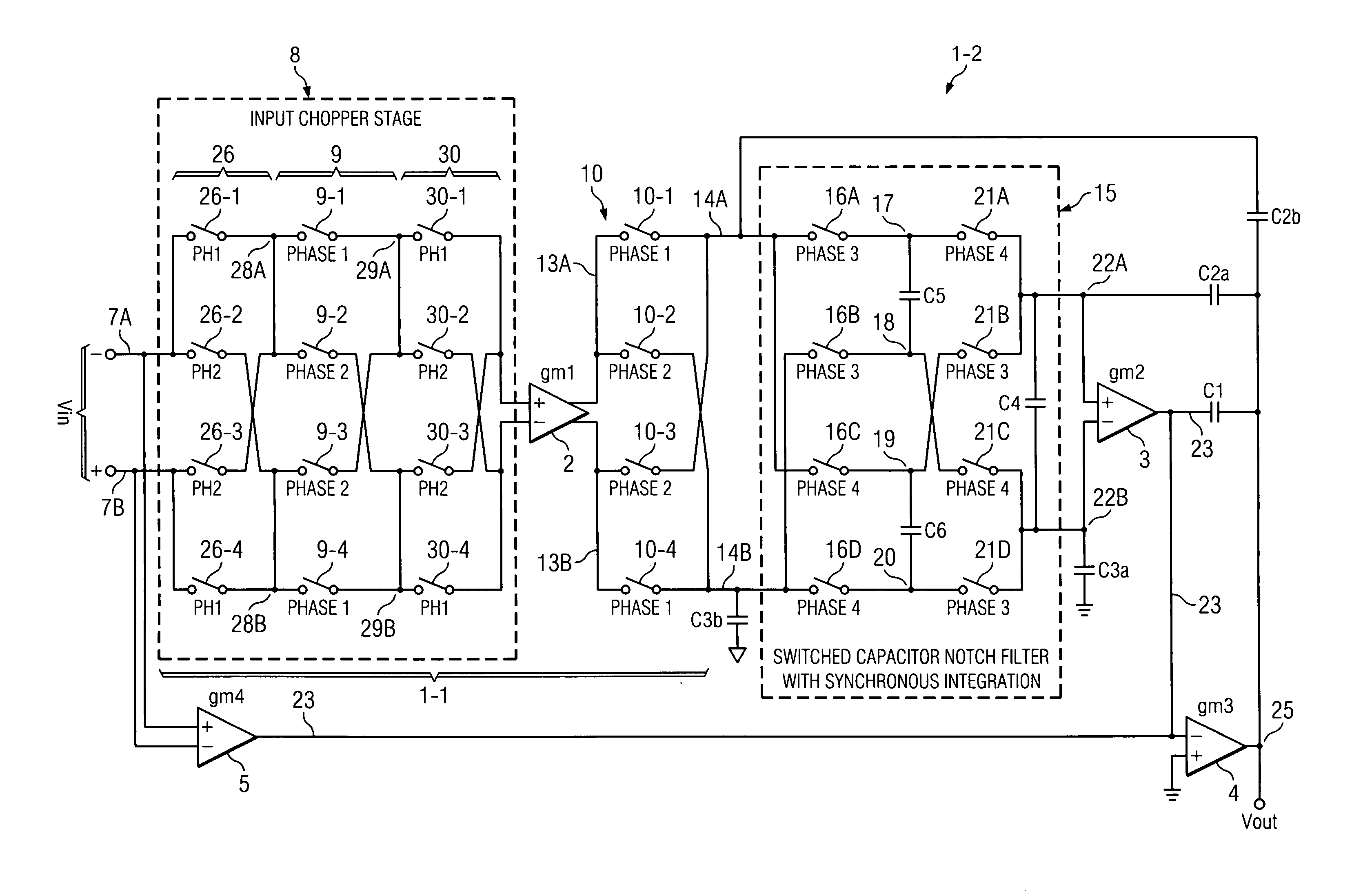
[0030]Referring to FIG. 3A, operational amplifier 1-1 includes (−) input conductor 7A and (+) input conductor 7B by means of which an input signal Vin is applied to input chopping stage 8, which includes a low-frequency pre-chopping circuit 26, a high-frequency chopping circuit 9, and a low-frequency post-chopping circuit 30. Pre-chopping circuit 26 includes switches 26-1 and 26-2 having first terminals connected to (−) input conductor 7A and switches 26-3 and 26-4 having first terminals connected to (+) input conductor 7B. Switches 26-1 and 26-3 have second terminals connected by conductor 28A to one input of input chopping circuit 9, and switches 9-2 and 9-4 have second terminals connected by conductor 28B to another input of input chopping circuit 9. Input chopping circuit 9 includes switches 9-1 and 9-2 having first terminals connected to conductor 28A and switches 9-3 and 9-4 having first terminals connected to conductor 28B. Switches 9-1 and 9-3 have second terminals connected...


PUM


Abstract

A chopper-stabilized circuit (1) includes pre-chopping circuitry (26) for chopping an input signal (Vin) at a first frequency to generate a first signal. Input chopping circuitry (9) chops the first signal at a second frequency substantially greater than the first frequency to produce a second signal. The first frequency is a sub-harmonic of the second frequency. Post-chopping circuitry (30) chops the second chopped signal at the first frequency to produce a third signal that is applied to an input of a signal conditioning circuit (2). The output chopping circuitry (10) chops an output of the signal conditioning circuit at the second frequency to generate a fourth signal. The fourth signal is filtered.

Description

BACKGROUND OF THE INVENTION[0001]The present invention relates generally to chopper-stabilized operational amplifiers. The invention also relates to chopper-stabilized operational amplifiers which include notch filters to reduce output ripple voltage due to the chopping signals. The invention relates more particularly to improvements which substantially reduce input bias current without necessarily decreasing chopping clock voltage level levels, without causing increased chopping-clock-induced ripple voltages, and / or without the need to increase notch filter capacitor size.[0002]Chopper-stabilized operational amplifiers used as stand alone operational amplifiers provide excellent offset voltage and offset voltage drift performance without the need for trimming of components to reduce offset and drift. This means that in addition to good DC performance, chopper-stabilized operational amplifiers also have advantages of reduced integrated circuit die size and lower product cost. Howeve...

Claims


Application Information

Patent Timeline
Patent Type & Authority Applications(United States)
IPC IPC(8): H03F1/02H03K17/00
CPCH03F3/005H03F2200/271H03F3/38
Inventor BURT, RODNEY T.ZHANG, JOY Y.
Owner TEXAS INSTR INC
Learn More