
LED light converting resin composition and LED member using the same

a technology of led light converting resin and resin composition, which is applied in the direction of instruments, discharge tubes luminescnet screens, lenses, etc., can solve the problems of reducing the optical characteristic and reliability of the product, requiring a relatively high manufacturing cost, and increasing the size of the product, so as to achieve simple and easy replacement of the lens, short life, and easy replacement

Active Publication Date: 2011-12-29
STCUBE +1
View PDF1 Cites 26 Cited by
  • Summary
  • Abstract
  • Description
  • Claims
  • Application Information

AI Technical Summary

Benefits of technology

[0027]Accordingly, the present invention has been made to solve the above-mentioned problems occurring in the prior art. A first object of the present invention is to epochally increase the life of an LED lighting device for white light emission, in which a long-life high-luminance LED (service life of about 100,000 hours), such as a blue LED, a violet LED, optionally a UV LED, instead of a conventional relatively short-life high-luminance white LED (service life of about 30,000 hours), is used to simply and easily obtain a white light or a yellowish white light for lighting.
[0028]Another object of the present invention is to allow a user or an operator, instead of a manufacturer, to directly and easily adjust a white light to a required intensity at a low cost, or obtain a mild white light by using a relatively inexpensive LED, such as a blue LED, a violet LED, or a UV LED, instead of a conventional expensive high-luminance white LED.
[0029]Further another object of the present invention is to effectively and easily remove a concern about non-uniformity in an emitted color, caused by non-uniform distribution or coating of a lighting color converting fluorescent substance.

Problems solved by technology

The method has a problem in that it requires a relatively high manufacturing cost, increases the size of a product due to a complicated operating circuit, and degrades an optical characteristic and reliability of the product due to a difference in the temperature characteristics of three LEDs, and thus is hardly used at present.
Thus, the method has a problem in that the life of the LED is significantly reduced to one third or less due to LED degradation caused by a reduction in heat dissipation.
However, it is very difficult to achieve homogeneous coating or dispersion / distribution of the fluorescent substance.
However, the white light includes mixed-lights having two wavelengths with incomplete complementarity, and thus has only a part of a visible region spectrum.
Thus, it does not satisfy a general indoor lighting.
Also, there is a problem in that the luminance is low because the blue LED shows the highest efficiency at an excitation light source of about 405 nm while the YAG-based fluorescent substance is excited by a blue light of 450˜460 nm.
Especially, in coating or molding of the YAG-based fluorescent substance, it is difficult to guarantee a homogeneous and uniform dispersibility.
This reduces the uniformity and reproducibility of a product, and significantly reduces the life of an LED, in the luminance and spectral distribution of a white light.
However, the utilization of the white LED has a problem in that the blue and green fluorescent substances show a satisfactory light-emitting efficiency while the red fluorescent substance shows a low light-emitting efficiency.
Especially, in a case of the UV LED, an organic resin is deteriorated by UV with a strong energy, thereby significantly reducing the life of the LED.
Especially, a white light emitted by the blue LED and the YAG-based fluorescent substance may have a problem in that the emitted color is generally inclined to blue or yellow due to the difficulty in the additive amount adjustment and the homogeneous dispersion of a yellow fluorescent substance.
Thus, it is difficult to obtain a white light having a high light characteristic.
Furthermore, it is not easy to precisely control a degree of dispersion of a fluorescent substance.
Accordingly, there is a problem in that it is not easy to fabricate a high-quality white LED device, and the fabrication reproducibility is not good.
However, since the light diffusing sheet 140 serves to convert the incident light into the homogenized light over the entire area of the display panel through the diffusion and scattering thereof, in the conventional back light unit, there are problems in that the thickness thereof is increased and durability and economic feasibility thereof is deteriorated owing to increase of man-hour and number of parts.

Method used


Image

  • LED light converting resin composition and LED member using the same
  • LED light converting resin composition and LED member using the same
  • LED light converting resin composition and LED member using the same

Examples


example 1

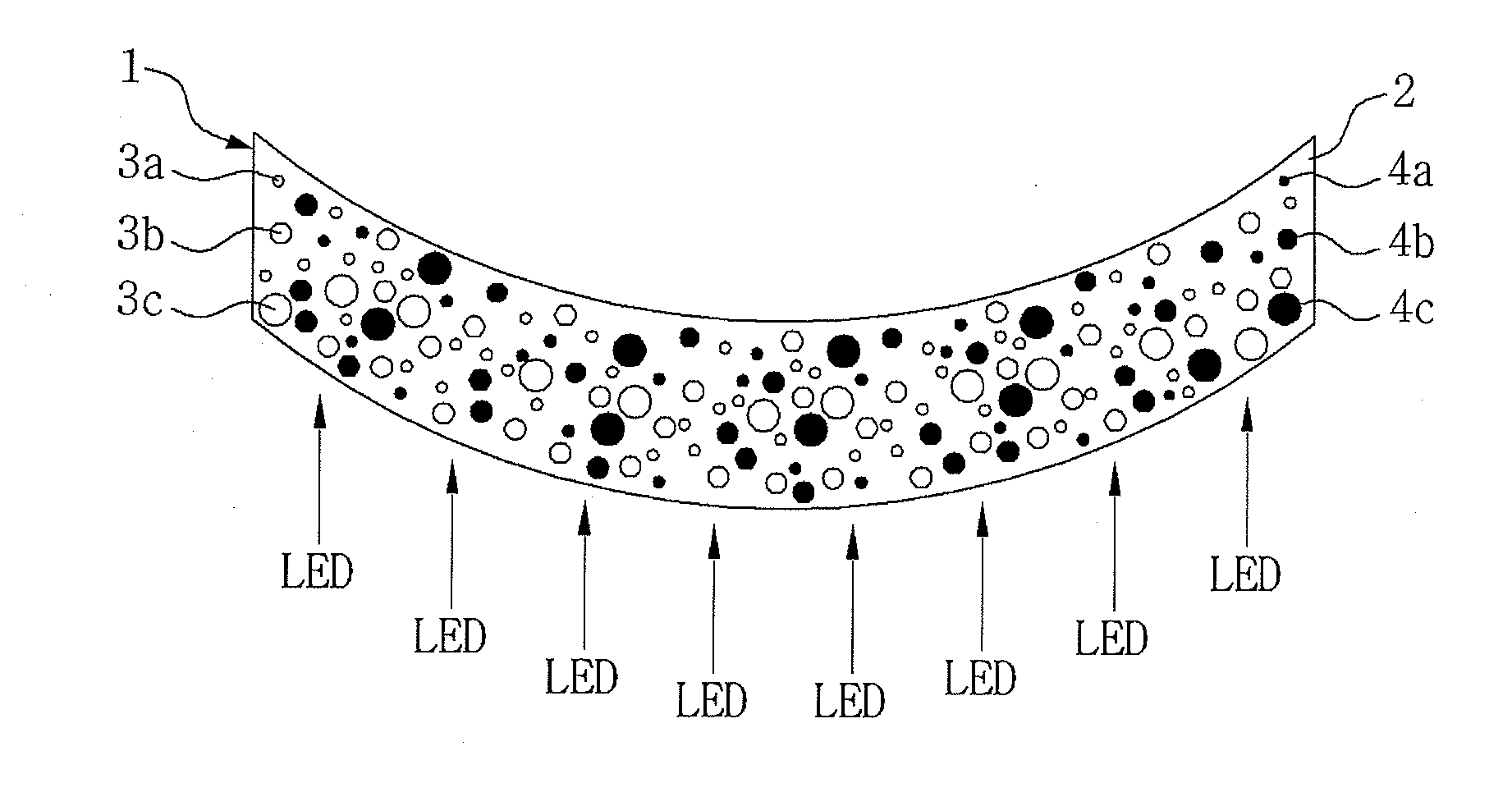
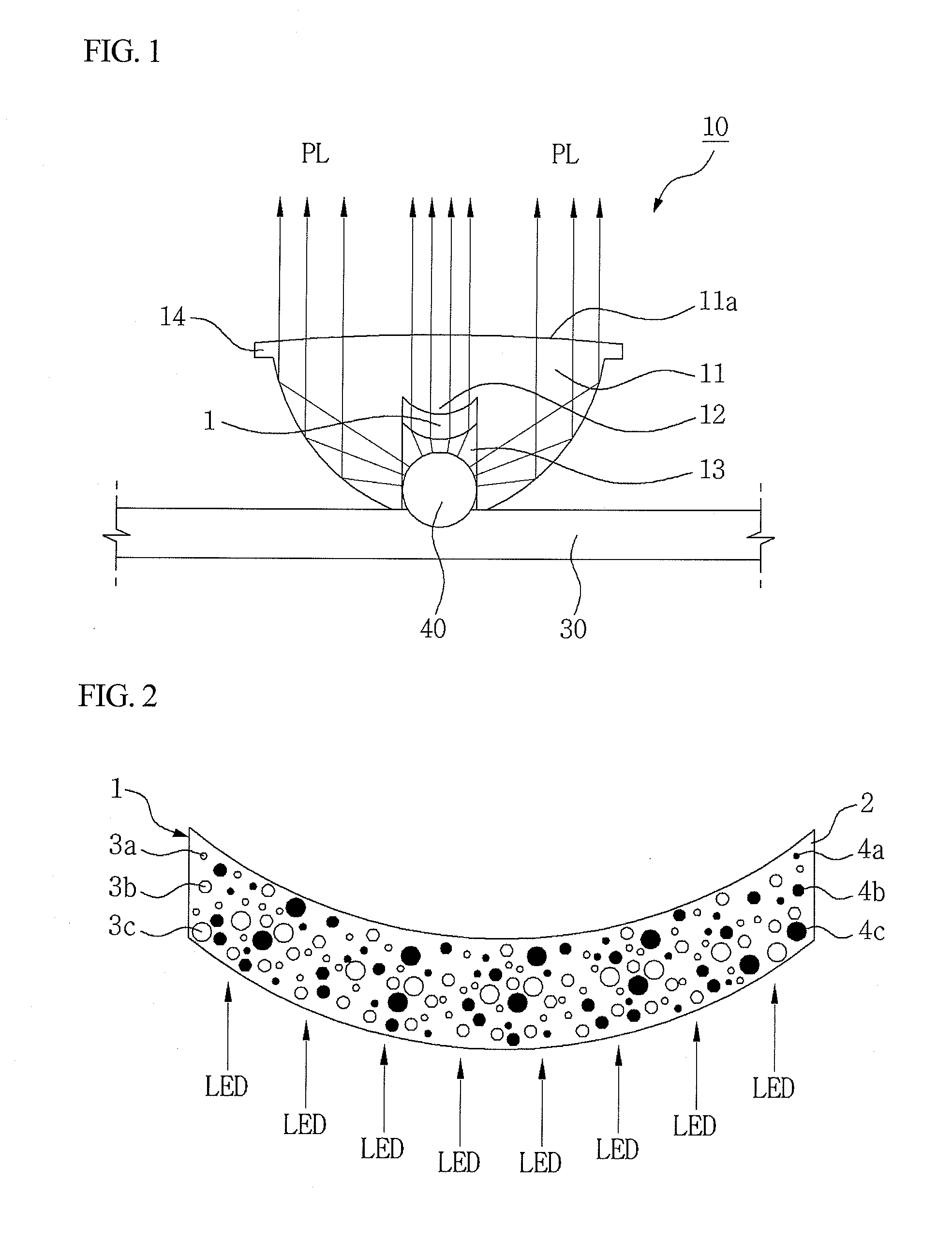
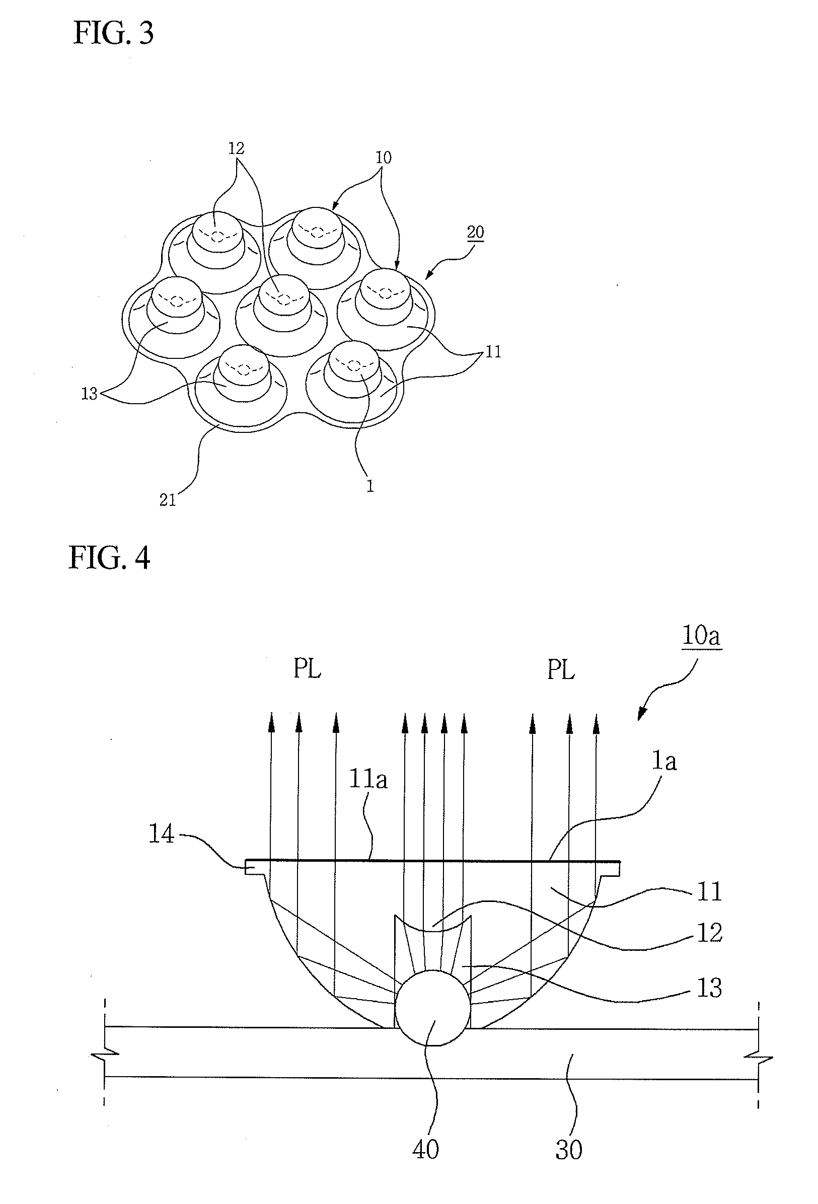
[0113]First, an LED lens cluster made of an epoxy resin, as shown in FIG. 3, was injection-molded. Then, a LED light converting resin composition for conversion of an emitted color, including 84 wt % of a silicon resin (Dow Corning Corp., 409 HS), 14 wt % of (YGd)3A15O12: Ce as a yellow fluorescent substance, and 2 wt % of polymethylmethacrylate with an average particle diameter 2.0 μm (refractive index: 1.50, light transmittance: 91%) as a light diffuser, was double-injection molded with a thickness of 2 mm within the LED mounting portion. The molded article was integrally formed with the LED lens.

[0114]The LED lens cluster manufactured as described above was mounted to the LED lighting device provided with a blue LED, as shown in FIG. 5. As a result, a slightly yellowish white light was obtained.

example 2

[0115]An LED lens cluster was manufactured in the same manner as in Example 1, except that a LED light converting resin composition for emitted-color conversion, includes 84 wt % of a silicon resin (Dow Corning Corp., 409 HS), 13.8 wt % of (YGd)3A15O12: Ce as a yellow fluorescent substance, 2 wt % of polymethylmethacrylate with an average particle diameter 2.0 μm as a light diffuser, and 0.2 wt % of naphthalazobenzene.

[0116]The LED lens cluster manufactured as described above was mounted to the LED lighting device provided with a blue LED, as shown in FIG. 5. As a result, a yellow light was obtained due to the addition of a pigment.

example 3

[0117]An LED lens cluster was manufactured in the same manner as in Example 1, except that a LED light converting resin composition includes 83 wt % of a polymethyl pentene resin (Mitsui Kagaku Co., Ltd., Japan, heat-resistance temperature: 200° C., MTS 284), 9 wt % of Y2O2S:Eu,Gd as a red fluorescent substance, 6 wt % of ZnS:Cu,Al as a green fluorescent substance, and 2 wt % of polymethylmethacrylate with an average particle diameter 2.0 μm as a light diffuser.

[0118]The LED lens cluster manufactured as described above was mounted to the LED lighting device provided with a blue LED, as shown in FIG. 5. As a result, a natural three-wavelength white light was obtained.


PUM


Abstract

Disclosed are an LED light converting resin composition, and an LED member using the same. The LED light converting resin composition comprises 20˜99 wt % of transparent resin, 0.8˜60 wt % of a lighting color converting fluorescent substance, and 0.2˜20 wt % of a light diffusing bead with an average particle diameter of 0.2˜30 μm. It is possible to emit a white or yellowish white light, like a conventional white light LED, only by independently using a white light emitting LED lens with no change in a blue, violet, or UV LED. There is no need to use a white LED which is relatively expensive and has a short life. Instead, as required, it is possible to easily replace a conventional LED lens with the disclosed LED lens by a user or an operator, thereby obtaining a mild white light with a required luminance. Thus, glaring, caused by a high-luminance white LED lighting, can be effectively reduced, thereby providing a milder lighting with improved comfort. Furthermore, the concern about the deterioration of a lighting device can be reduced due to a high heat-resistance, which increases economical efficiency.

Description

BACKGROUND OF THE INVENTION[0001]1. Field of the Invention[0002]The present invention relates to an LED (Light Emitting Diode) light converting resin composition, and an LED member using the same. More particularly, the present invention relates to a LED light converting resin composition obtained by mixing a heat-resistant transparent matrix resin with a color converting fluorescent substance, and a light diffusing bead, optionally together with a pigment, and an LED member using the same, such as an LED lens or a light guide plate.[0003]2. Description of the Prior Art[0004]An LED is a kind of semiconductor device which converts electrical energy to light energy by using a characteristic of a semiconductor including a specific compound. The LED is advantageous in that its power consumption is very small due to high photoconversion efficiency, it is appropriate for miniaturization, slimming, and light-weighting, due to its small size light source and at the same time can be unlimite...

Claims


Application Information

Patent Timeline
Patent Type & Authority Applications(United States)
IPC IPC(8): G02B3/00G02B5/23
CPCH01L33/505G02B1/041
Inventor SHIM, HYUN-SEOP
Owner STCUBE
Learn More