UV coating composition for LED color conversion

a technology of led coating and color conversion, which is applied in the direction of instruments, optical elements, planar/plate-like light guides, etc., can solve the problems of increasing product size, low optical characteristics and reliability of products, and requiring a relatively high manufacturing cost, so as to achieve simple and easy replacement of lenses and short lifespan

Inactive Publication Date: 2013-10-01
STCUBE
View PDF8 Cites 5 Cited by
  • Summary
  • Abstract
  • Description
  • Claims
  • Application Information

AI Technical Summary

Benefits of technology

[0034]With the UV coating composition for LED color conversion according to the present invention, a lighting device can emit white light, as in a conventional white light LED, independently using only a white LED lens or a light guide plate without affecting a blue, violet or UV LED, thereby eliminating a need for a white LED which is relatively expensive and has a short lifespan of about ⅓ that of other kinds of LEDs. Further, when the lighting device employs a conventional blue, violet, or UV LED having a long lifespan, the UV coating composition of the present invention allows the lighting device to obtain white light by simply and easily replacing a lens. Thus, an LED lens comprising the UV coating composition of the present invention allows a user or an operator, instead of a manufacturer, to perform direct and easy adjustment of the intensity of white light to a desired intensity by replacing a conventional LED lens, and makes it possible to provide soft and comfortable lighting by effectively reducing glare caused by high brightness white LED lighting. Furthermore, the UV coating composition of the present invention may provide a backlight unit having a simple and thin structure for a display device and may reduce a possibility of deterioration of a lighting device or a display device by ensuring high heat resistance, thereby providing high efficiency and economic feasibility.

Problems solved by technology

However, this method has problems in that it requires a relatively high manufacturing cost, increases product size due to a complicated operating circuitry, and provides low optical characteristics and reliability of the product due to difference in temperature characteristics of the three LEDs, and thus is not substantially used at present.
Thus, this method has a problem in that the lifespan of the LED is significantly reduced to one third or less due to LED degradation resulting from deterioration in heat dissipation.
Particularly, when the phosphor is not evenly coated or dispersed, luminescent colors becomes non-uniform.
However, it is very difficult to achieve uniform coating or dispersion / distribution of the phosphor.
However, the white light results from a mixture of the light components, which have different wavelengths and are not in a complete completely complementary relationship, and thus has only part of a visible range spectrum.
Thus, it does not satisfy requirements for general indoor lighting.
Also, the white LED has a problem of low brightness, because the blue LED shows the highest efficiency by excitation light at a wavelength of about 405 nm whereas the YAG-based phosphor is excited by blue light in a wavelength band of 450˜460 nm.
Particularly, in coating or molding of the YAG-based phosphor, it is difficult to guarantee homogeneous and uniform dispersibility, thereby deteriorating uniformity and reproducibility of products in terms of brightness and spectral distribution of white light, and significantly reducing the lifespan of the LED.
However, the use of the white LED has a problem in that the blue and green phosphors have satisfactory light emission efficiency while the red phosphor has low light emission efficiency.
Particularly, the UV LED tends to deteriorate an organic resin by UV having a strong energy, thereby significantly reducing the lifespan of the LED.
Particularly, white light emitted by combination of the blue LED and the YAG-based phosphor may have a problem in that the emitted color is generally biased to blue or yellow color due to difficulty in adjustment of the amount of a yellow phosphor and uniform dispersion thereof.
However, in a fabrication process, before the matrix resin is completely hardened, a phosphor having a much higher specific gravity (the phosphor has a specific gravity of about 3.8˜6.0, although it depends on the kind of the phosphor) than the matrix resin is precipitated in a lower region of the light-transmitting matrix resin having a low specific gravity (for example, an epoxy resin has a specific gravity of about 1.1˜1.5), thereby making it difficult to obtain white light having excellent luminescent characteristics.
Furthermore, it is not easy to precisely control the degree of dispersion of the phosphor.
Accordingly, it is not easy to fabricate a high-quality white LED device and fabrication reproducibility is not good.
Since the light diffusing sheet 40 serves to convert incident light into uniform light over the entire area of a display panel through diffusion and scattering, stacking the light diffusing sheet 40 on the prism sheet 30 makes it difficult to reduce the thickness of the backlight unit and increases the number of processes and components, causing deterioration in economic feasibility and process efficiency.

Method used


Image

  • UV coating composition for LED color conversion
  • UV coating composition for LED color conversion
  • UV coating composition for LED color conversion

Examples


example 2

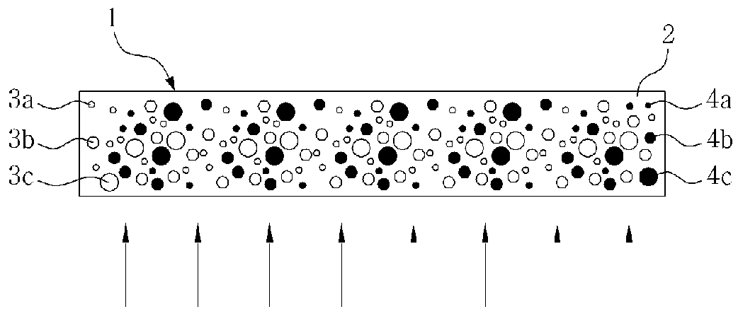
[0089]An LED lens was formed using an epoxy resin through injection molding, and a mixture of 92 wt % of an epoxy acrylate monomer and an oligomer (containing 3.5 wt % of alpha-hydroxyketone as a photoinitiator), 6 wt % of (YGd)3Al5O12:Ce as a yellow phosphor, and 2 wt % of polymethyl (meth)acrylate having an average particle diameter of 2.0 μm (index of refraction: 1.50, light transmittance: 91%) as light diffusing beads was deposited on an upper surface of the LED lens and subjected to irradiation using a xenon lamp with an exposure of 890 mJ for 30 seconds, thereby forming a 85 μm thick UV coating layer for LED color conversion.

[0090]The prepared LED lens was mounted on a blue LED. Upon operation of the LED, white light was obtained.

example 3

[0091]A UV coating layer for LED color conversion was formed on a flat upper surface of an epoxy LED lens by the same method as in Example 1, except that a mixture of 87 wt % of an urethane acrylate monomer and an oligomer (containing 1.8 wt % of phenylglyoxylate as a photoinitiator), 7 wt % of Y2O2S:Eu,Gd as a red phosphor, 3 wt % of ZnS:Cu,Al as a green phosphor, and 3 wt % of polymethyl (meth)acrylate having an average particle diameter of 2.0 μm as light diffusing beads was deposited on the flat upper surface of the LED lens.

[0092]The prepared LED lens was mounted on a blue LED. Upon operation of the LED, white light was obtained.

example 4

[0093]A UV coating layer for LED color conversion was formed on a flat upper surface of an epoxy LED lens by the same method as in Example 1, except that a mixture of 92.5 wt % of an acryl acrylate monomer and an oligomer (containing 1.5 wt % of phenylglyoxylate as a photoinitiator), 3 wt % of LiAlO2:Mn as a red phosphor, 2 wt % of Y3(GaxAl1-x)5O12:Ce (010O17 as a blue phosphor, and 1.5 wt % of polymethyl (meth)acrylate having an average particle diameter of 2.0 μm as light diffusing beads was deposited on the flat upper surface of the LED lens.

[0094]The prepared LED lens was mounted on a violet LED. Upon operation of the LED, white light was obtained.


PUM

PropertyMeasurementUnit
wt %aaaaaaaaaa
particle diameteraaaaaaaaaa
particle diametersaaaaaaaaaa

Abstract

A UV coating composition for LED color conversion including: 25 wt % to 97 wt % of a UV curable resin; and 3 wt % to 75 wt % of a phosphor. The composition enables emission of white light using only a white LED lens or a light guide plate without affecting a blue, violet or UV LED, thereby eliminating a need for a white LED. Further, users of a LED including the composition can perform direct and easy adjustment of the intensity of white light to obtain a desired intensity by replacing a conventional LED lens. The LED lens provides soft and comfortable lighting which effectively reduces glare caused by high brightness white LED lighting. Moreover, the composition slows deterioration of a lighting device and makes possible a light guide plate having a simple and thin structure.

Description

CROSS REFERENCE TO RELATED APPLICATIONS[0001]This application is a National Stage of International Application No. PCT / KR2010 / 005285, filed on Aug. 12, 2010, which claims priority to Korean Application No. 10-2010-0016560 filed Feb. 24, 2010, and Korean Application No. 10-2010-0026164 filed Mar. 24, 2010. The content of the prior applications are incorporated herein by reference in their entirety.TECHNICAL FIELD[0002]The present invention relates to a UV coating composition for LED (light emitting diode) color conversion. More particularly, the present invention relates to a UV coating composition for LED color conversion, which includes a phosphor for color conversion and, optionally, a light diffusing bead and / or a pigment, in a heat-resistant transparent UV-curable matrix resin to allow white light for lighting or a display device to be obtained through a simple and inexpensive structure from a high brightness blue LED, violet LED or UV LED having a long lifespan without using an...

Claims


Application Information

Patent Timeline
Patent Type & Authority Patents(United States)
IPC IPC(8): C09K11/02
CPCC09D7/1275C09D7/1283C09D133/04C09K11/613C09K11/641C09K11/642C09K11/7407C09K11/7701C09K11/7706C09K11/7731C09K11/7734C09K11/7774C09K11/7784G02B6/0068G02B6/0023C08L33/12G02B6/0016G02B6/0038G02B6/0046G02B6/0073Y02B20/181H01L33/501H01L33/502C08F2222/1086C08F2222/1093C08K3/0075C08K3/10C09D7/68C09D7/69C08F222/1067C08F222/1065Y02B20/00
Inventor SHIM, HYUN-SEOP
Owner STCUBE
Why Eureka
Try Eureka