Ultrasonic sensor, measuring device, and measurement system

a technology of ultrasonic sensor and measuring device, which is applied in the field of ultrasonic sensor, measuring device, and measuring system, can solve the problems of inability to easily identify if, inability to set the transducer, and difficulty in operation of the device, so as to increase the versatility of the system, reduce the size and thickness of the ultrasonic sensor, and facilitate calculation

Active Publication Date: 2011-12-29
SEIKO EPSON CORP
View PDF2 Cites 12 Cited by
  • Summary
  • Abstract
  • Description
  • Claims
  • Application Information

AI Technical Summary

Benefits of technology

[0041]In this measurement system, as in the measurement device described above, the position and axial direction of an object to be detected can be easily calculated and determined from the ultrasonic wave reflection positions at two points on the object to be detected by the ultrasonic sensor.
[0042]Because various types of signal processing are performed by the control device, various types of calculation circuits do not have to be disposed in the ultrasonic sensor, and the size and thickness of the ultrasonic sensor can be reduced. This increases the versatility of the system. For example, when the position of a blood vessel inside the body is to be determined using this configuration, the probe can be attached to the body using tape.

Problems solved by technology

However, it cannot be easily identified if the user is a person without specialized knowledge.
Therefore, such a device is difficult to operate correctly if the user is a person without specialized knowledge, even though it can be easily operated by a person with specialized knowledge.
In these situations, the direction of the transducer cannot be set with respect to the axial direction of the blood pressure, and accurate measurement results cannot be obtained.
As a result, the configuration is complicated and increases manufacturing costs.
However, in such applications as well, the wiring configuration for the ultrasonic transducers in the two-dimensional array is complicated and increases manufacturing costs.

Method used


Image

  • Ultrasonic sensor, measuring device, and measurement system
  • Ultrasonic sensor, measuring device, and measurement system
  • Ultrasonic sensor, measuring device, and measurement system

Examples


first embodiment

[0062]The following is a description made with reference to the drawings of a biological testing device or measuring device equipped with the ultrasonic sensor in the first embodiment of the present invention.

1. Overall Configuration of Biological Testing Device

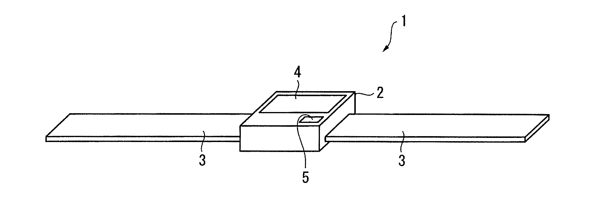
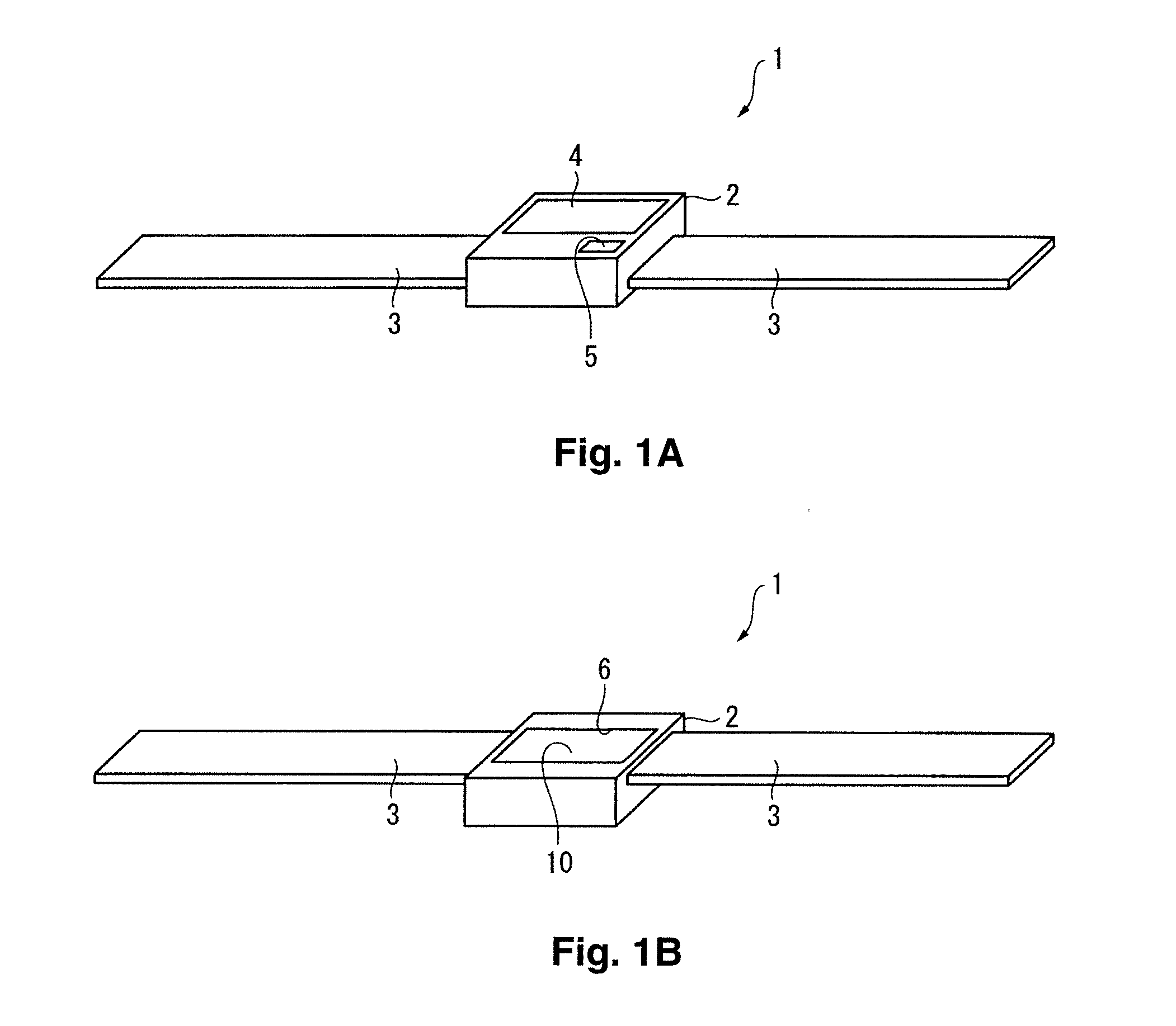
[0063]FIGS. 1A and 1B are perspective views showing an outline of the biological testing device in the first embodiment in which FIG. 1A is a view from the obverse side of the biological testing device, and FIG. 1B is a view from the reverse side of the biological testing device.

[0064]In FIG. 1, the biological testing device 1 measures the conditions in a blood vessel such as the blood flow, blood pressure and pulse using ultrasound. More specifically, as shown in FIG. 1, the biological testing device 1 has a device main unit 2 and a band 3 connected to the device main unit 2. The reverse side of this biological testing device 1 pressed against the body and fastened using the band 3, for example, to monitor and measure the co...

second embodiment

[0155]The following is an explanation with reference to the drawings of the biological testing device in the second embodiment of the present invention.

[0156]The biological testing device in the second embodiment has an ultrasonic array 12 configuration that is a variation on the biological testing device in the first embodiment. The rest of the configuration is identical to the one in the biological testing device of the first embodiment.

[0157]FIG. 11 is a top view of the substrate 11 of the probe 10 in the biological testing device in the second embodiment of the present invention. In FIG. 11, the biological testing sensor 13 has been omitted. In the explanation of the second and subsequent embodiments, an explanation of the components with the same numbers has been omitted or simplified in configurations similar to the first embodiment.

[0158]As in the first embodiment, ultrasonic arrays 31 (31A, 31B, 31C, 31D) are arranged in the central position of each side 11A-11D of the subst...

third embodiment

[0173]The following is an explanation with reference to the drawings of the biological testing device in the third embodiment of the present invention.

[0174]The biological testing device in the second embodiment has an ultrasonic array 12 configuration that is a variation on the biological testing device in the first embodiment. The rest of the configuration is identical to the one in the biological testing device of the first embodiment.

[0175]FIG. 14 is a cross-sectional view and a top view showing a simplified configuration of the probe 10 in the third embodiment of the present invention.

[0176]In the biological testing device of the third embodiment, three ultrasonic arrays 12 are arranged on each side 11A-11D of the substrate 11 of the probe 10. These ultrasonic arrays 12 are arranged at positions apart from one another, and wiring patterns for a biological testing sensor not shown in the drawing and wiring patterns for the ultrasonic arrays 12 are formed in the spaces between ul...


PUM


Abstract

An ultrasonic sensor has two or more ultrasonic arrays disposed on a probe surface, and a delay control unit that controls a transmission angle of ultrasonic waves transmitted from the ultrasonic arrays. The ultrasonic arrays have a linear array structure in which a plurality of ultrasonic elements are arranged in a linear scanning direction, and the delay control unit controls the timing for transmitting ultrasonic waves from the ultrasonic elements and controls the transmission angle of the ultrasonic waves transmitted from the ultrasonic arrays. Two of the ultrasonic arrays have linear scanning directions that are different from each other and are arranged in positions that are spaced apart from each other.

Description

CROSS-REFERENCE TO RELATED APPLICATIONS[0001]This application claims priority to Japanese Patent Application No. 2010-145106 filed on Jun. 25, 2010. The entire disclosure of Japanese Patent Application No. 2010-145106 is hereby incorporated herein by reference.BACKGROUND[0002]1. Technical Field[0003]The present invention relates to an ultrasonic sensor, a measuring device, and a measurement system able to detect the position of an object to be detected using ultrasound.[0004]2. Related Art[0005]There are devices that use ultrasound to detect the state of an object to be detected such as a blood vessel in the human body (e.g., see Japanese Laid-Open Patent Application Publication No. 2005-34543).[0006]The device described in Japanese Laid-Open Patent Application Publication No. 2005-34543 has a probe in which a transducer has been disposed longitudinally parallel to the axial direction of a blood vessel. From the probe, a blood vessel diameter-detecting ultrasonic beam is transmitted...

Claims


Application Information

Patent Timeline
Patent Type & Authority Applications(United States)
IPC IPC(8): A61B8/00
CPCA61B8/04A61B8/06A61B8/4227A61B8/4477A61B8/4472A61B8/4483A61B8/4461
Inventor TSURUNO, JIRO
Owner SEIKO EPSON CORP
Why Eureka
Try Eureka