Check patentability & draft patents in minutes with Patsnap Eureka AI!

Method for producing metal thin film

a metal thin film and metal technology, applied in the direction of lithography, rotary lithographic machines, printing, etc., can solve the problems of difficult alignment of patterns, difficult to keep uniform, and illegible portions of patterns, so as to achieve scaled-down patterns and reduce thickness , the effect of low resistan

Inactive Publication Date: 2012-01-05
SONY CORP
View PDF10 Cites 2 Cited by
  • Summary
  • Abstract
  • Description
  • Claims
  • Application Information

AI Technical Summary

Benefits of technology

The patent text describes a method for producing a metal thin film by applying an ink containing a catalyst material to a flat blanket and then transferring the ink to a substrate using pressure compression. The ink is selectively transferred to the substrate in a region where the ink is applied, resulting in a metal thin film with low resistance and a high yield. The method also reduces the number of steps required to produce the thin film and ensures uniform contact pressure between the blanket and the substrate.

Problems solved by technology

Consequently, it is difficult to keep uniform the contact pressure of the cylindrical blanket to the whole of a substrate which is flat during the transfer to the substrate, and a portion of the pattern becomes illegible.
In addition, in bringing the cylindrical blanket and the flat substrate into contact, the alignment of them is not easy.
Further, the ink is a mixture of the conductive fine particles and resin, and hence the ink applied to the blanket has an increased thickness, making it difficult to achieve a scaled-down pattern.

Method used


Image

  • Method for producing metal thin film
  • Method for producing metal thin film
  • Method for producing metal thin film

Examples


example 1

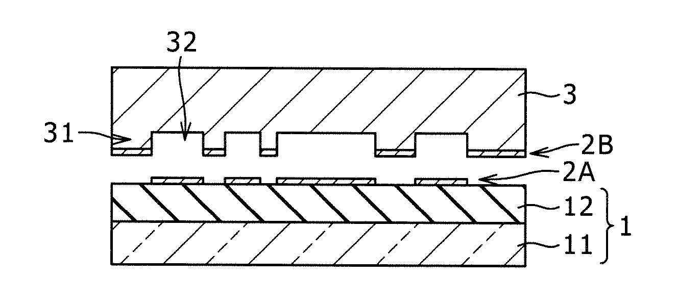
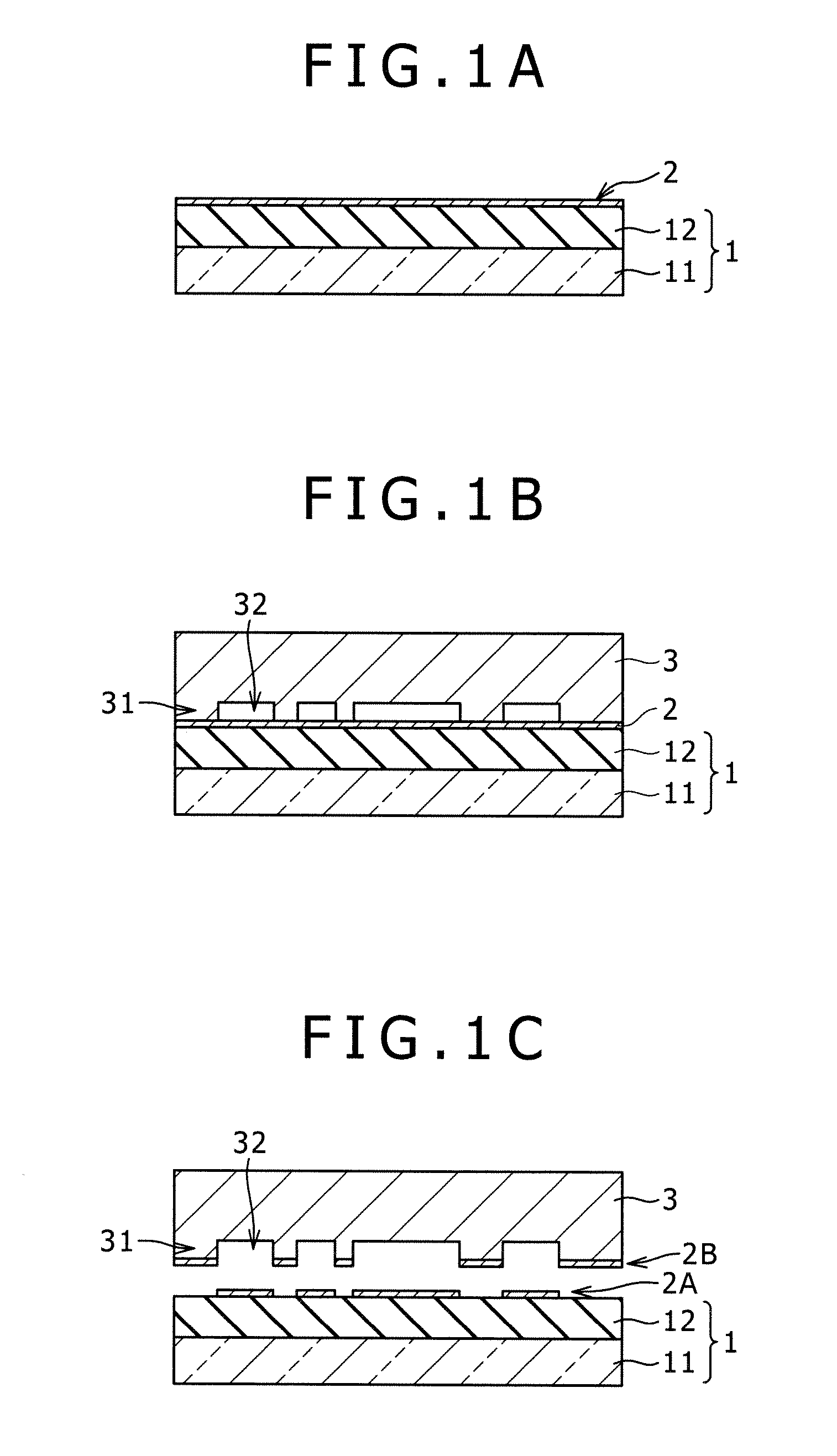
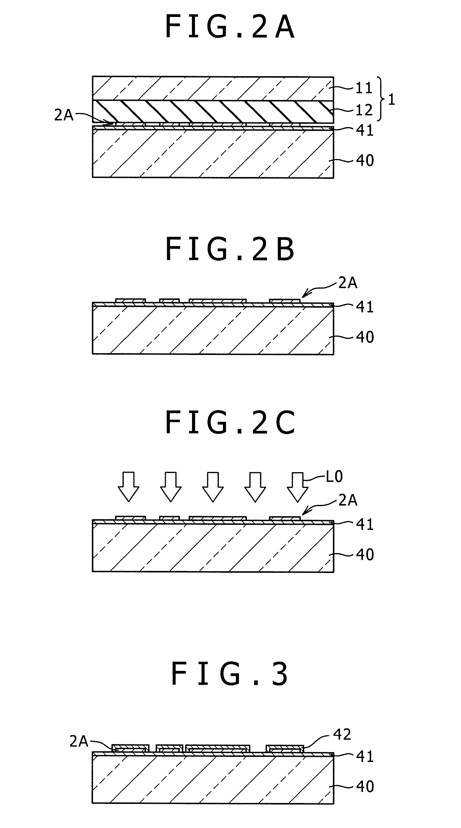
[0063]A metal thin film having a structure shown in FIG. 3 was formed as follows. Specifically, an ink 2 including a palladium (Pd) particle colloid, which is a metal compound corresponding to a catalyst material for the electroless plating, was prepared, and the ink 2 was printed on a substrate 40 by a reverse offset printing method, and then a Cu thin film was selectively deposited on the ink by Cu electroless plating to form a Cu wiring.

[0064]The ink 2 contained a Pd particle colloid {hydrophobic Pd decylamine (DA) colloid toluene solution, manufactured and sold by Tanaka Kikinzoku Kogyo} which is a metal compound corresponding to a catalyst material for the electroless plating, and the Pd particle colloid treated by the following procedure was used. The hydrophobic Pd DA colloid toluene solution was first adjusted in concentration to 1.0% by weight, and n-hexadecanethiol was added to the solution so that the concentration became 2.0% by weight, and the resultant mixture was heat...

example 2

[0073]A metal thin film was formed in substantially the same manner as in Example 1 except for the items shown below. Specifically, an ink 2 including Pd nanoparticles (protective agent: C16H33SH), which are metal nanoparticles corresponding to a catalyst material for the electroless plating, was prepared, and the ink 2 was printed on a substrate 40 by a reverse offset printing method, and then an Ni thin film was selectively deposited on the ink by Ni electroless plating to form an Ni wiring.

[0074]The ink 2 contained Pd nanoparticles (protective agent: C16H33SH) having an average particle size of 8 nm, which are metal nanoparticles corresponding to a catalyst material for the electroless plating, dispersed in tetrahydrofuran in a concentration of 1.0% by weight.

[0075]In this Example, an alignment mark was formed on the substrate 40 in advance, and the alignment accuracy in the printing was evaluated. In the printing step, as shown in FIG. 10, in the stage for fixing and pushing the...


PUM


Abstract

A method for producing a metal thin film on a substrate includes: a step of applying an ink to a flat blanket; a first transfer step of bringing the first blanket and a letterpress having a predetermined pattern of projections into contact by a pressure compression while the flat blanked and the letterpress being disposed opposite each other, to selectively transfer a portion of the ink on the flat blanket corresponding to the projections to the letterpress; a second transfer step of bringing the flat blanket obtained after the first transfer step and the substrate into contact by pressure compression while the flat blanket and the substrate being disposed opposite each other, to transfer the ink remaining on the flat blanket to the substrate; and a step of subjecting the substrate obtained after the second transfer step to electroless plating to deposit a metal thin film on the substrate.

Description

CROSS-REFERENCE TO RELATED APPLICATIONS[0001]This application is a continuation of U.S. application Ser. No. 12 / 157,473, filed Jun. 11, 2008, and entitled “Method for Producing Metal Thin Film.” This application also claims the benefit of priority of Japanese patent application number 2007-158341, filed in the Japanese Patent Office on Jun. 15, 2007, which is hereby incorporated by reference to the maximum extent allowable by law.BACKGROUND OF THE INVENTION[0002]1. Field of the Invention[0003]The present invention relates to a method for producing a metal thin film using a reverse offset printing method.[0004]2. Description of Related Art[0005]Some methods for producing a thin film pattern utilizing a reverse offset printing method have been proposed (for example, Patent Unexamined Patent Application Publication No. 11-58921(hereinafter referred to as “Patent Document 1” and Patent Unexamined Patent Application Publication No. 2006-278845(hereinafter referred to as “Patent Document ...

Claims


Application Information

Patent Timeline
Patent Type & Authority Applications(United States)
IPC IPC(8): B41F7/02B41F3/34
CPCH05K3/046H05K3/182H05K2203/074H05K2203/0108H05K2203/0709H05K3/207
Inventor TANAKA, MASANOBUISHIHARA, HIROTSUGUSHIMAMURA, TOSHIKIKAMEI, TAKAHIRO
Owner SONY CORP
Features
  • R&D
  • Intellectual Property
  • Life Sciences
  • Materials
  • Tech Scout
  • Unparalleled Data Quality
  • Higher Quality Content
  • 60% Fewer Hallucinations
Learn More