Cyclonic separator

a cyclonic separator and separator technology, applied in the direction of centrifugal force sediment separation, water/sludge/sewage treatment, moving filter element filters, etc., can solve the problems of increased maintenance activities, unavoidable water contaminant in fuel, operational delays, etc., to prevent water condensation within the tank, reduce maintenance costs, and reduce maintenance costs

Active Publication Date: 2012-01-05
AIRBUS OPERATIONS LTD
View PDF1 Cites 12 Cited by
  • Summary
  • Abstract
  • Description
  • Claims
  • Application Information

AI Technical Summary

Benefits of technology

[0012]In operation, water or ice naturally occurring in the fuel, and which is denser than the fuel, will be separated or at least concentrated by the cyclonic separator to form a water rich fuel mixture which can be fed to the engine to be burnt off. The less dense purified fuel exiting from the second outlet of the cyclonic separator is preferably fed back into the fuel tank. The concentration of water in the water rich fuel mixture is preferably several orders of magnitude higher than that of the fuel in the tank and so water is removed more quickly from the fuel tank by the fuel system of the present invention. By removing water from the tank, rather than merely dispersing condensation back into the tank, the concentration of water in the tank is kept low and problems associated with water condensation within the tank are prevented, even at low temperatures.
[0013]In relation to an aircraft fuel system, the lowest temperatures within the tank are encountered during the cruise portion of flight and so the cyclonic separator is preferably operated during the cruise, so as to remove water when condensation would otherwise most likely occur. It is preferable to remove the water when the water is suspended in the fuel. Once condensation occurs and water droplets have coalesced into larger droplets, pools and films, water is not readily re-dissolved in the fuel, even when the fuel temperature is raised increasing the solubility of water in fuel. Further devices, such as water scavenging lines, may be required if the water were to be allowed to condense and pool within the tank, leading to increased weight and cost. Since the concentration of water in the water rich fuel is initially much higher than that in the tank, the rate of removal of the water may be initially high and decreases as the water content of the fuel in the tank decreases. Removing water quickly at the start of operation of the cyclonic separator minimises water accumulation in the tank, before the lowest tank temperatures are reached. Although the cyclonic separator is preferably operated during the cruise, it may be operated during any phase of the flight (taxi, take-off, cruise or land). For example, water may be induced from a fuel tank sump into an induction line by a jet pump during the early phase of the flight (taxi and take-off) and discharged with motive flow to the cyclonic separator.

Problems solved by technology

Water is an unavoidable contaminant in fuel.
Water can affect components in fuel systems and lead to operational delays and increased maintenance activities.
Although water may affect fuel systems of land or water based vehicles, water is a particular problem in aircraft fuel systems.
With the droplet size of the order of microns, it takes a long time for the droplets to settle out to the tank bottom.
However, the low concentration of water in suspension means that the rate of water removal from the fuel system is slow.
Water from these pools can be drained off when the aircraft is on the ground but this is time consuming and costly, leading to a loss of operational efficiency.
In the case of exhausting to the atmosphere, a suitable exhaust system will be required, which adds weight, maintenance costs etc. to the fuel system and could lead to icing problems at the outlet.

Method used


Image

  • Cyclonic separator
  • Cyclonic separator
  • Cyclonic separator

Examples


Embodiment Construction

)

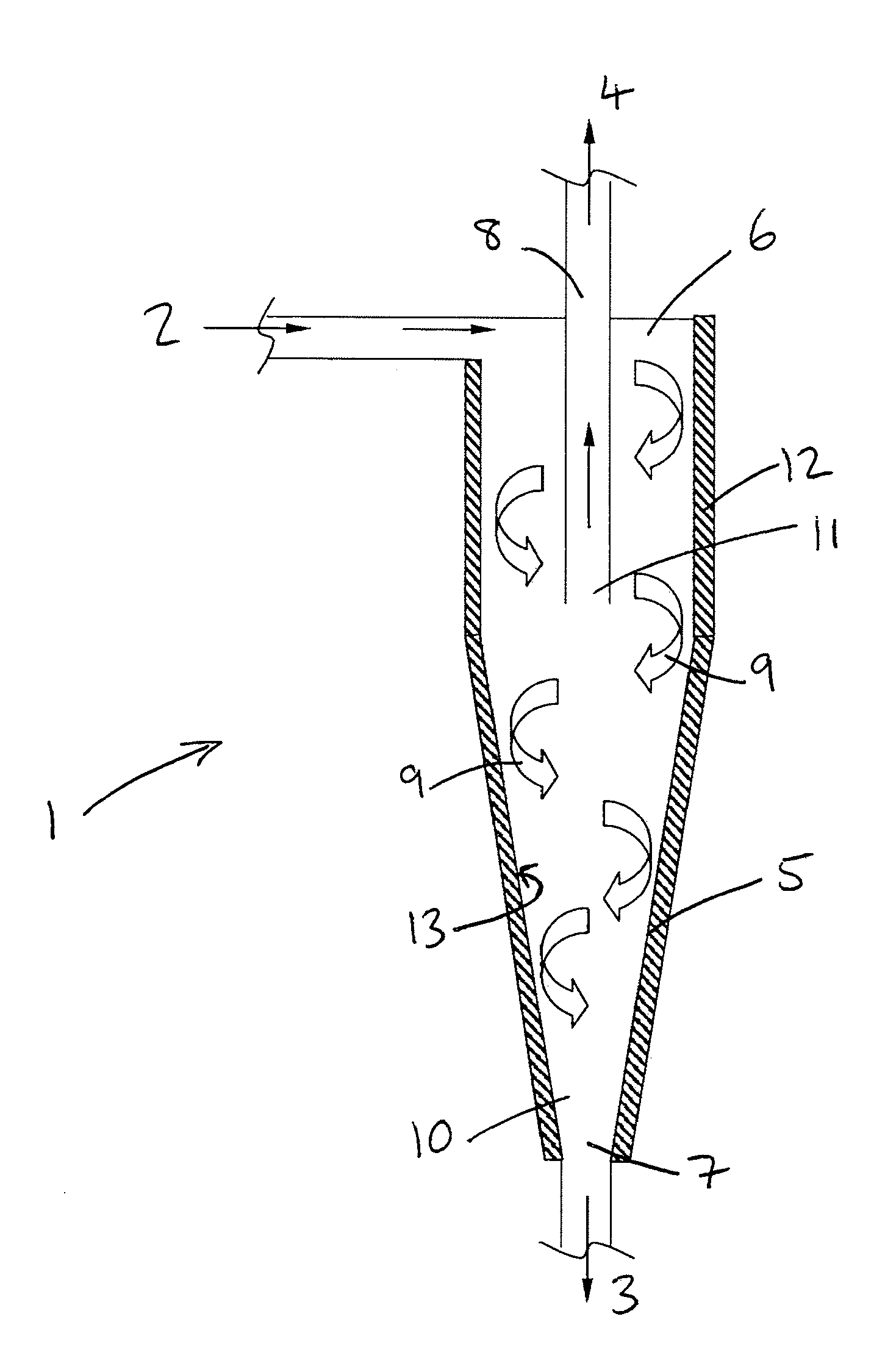
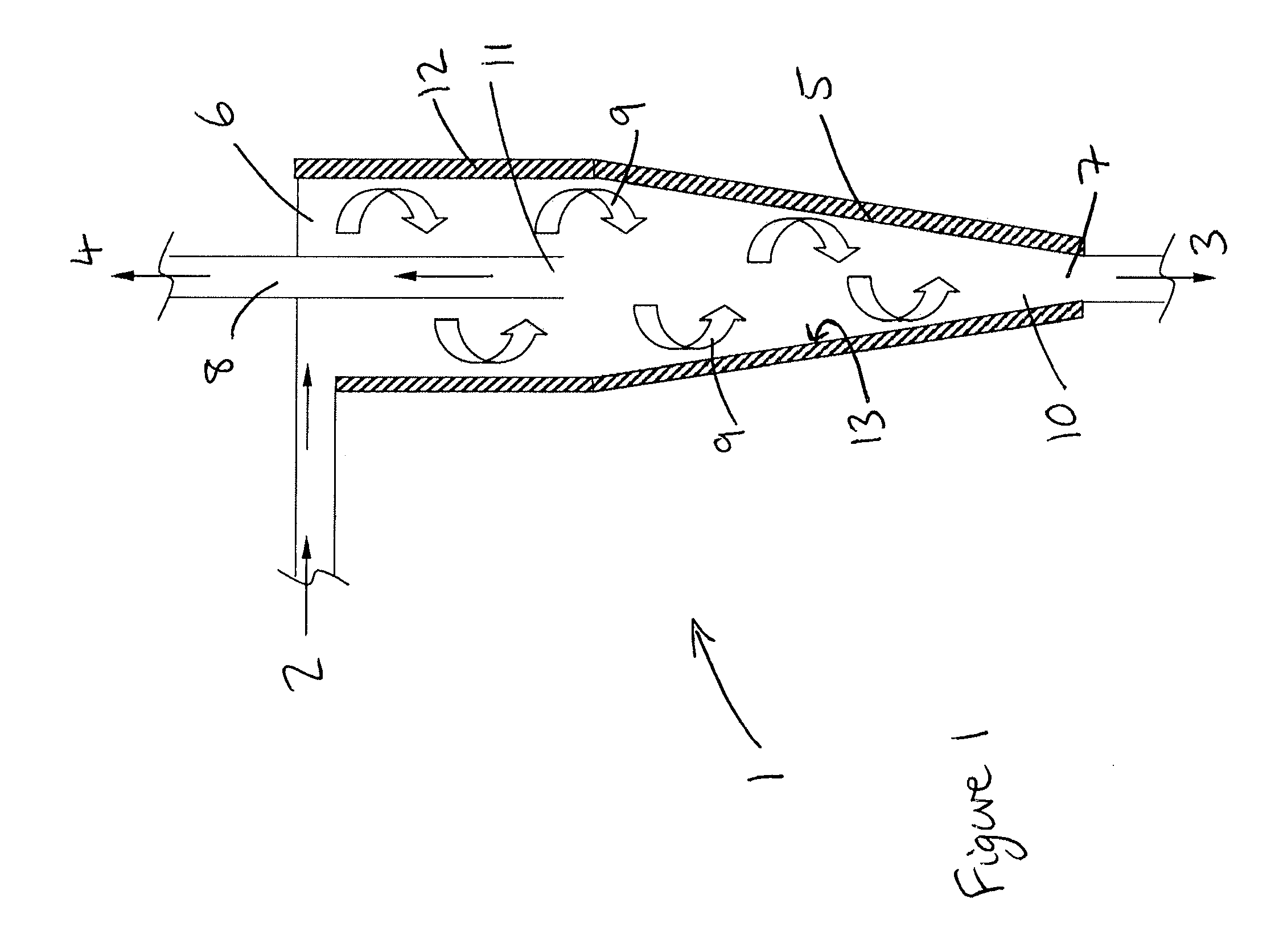
[0035]FIG. 1 illustrates schematically a cyclonic separator 1 having an inlet 2, a first outlet 3 and a second outlet 4. The cyclonic separator 1 has a cylindrical upper portion and a conical lower portion. The conical lower portion has a conical housing 5 having a downwardly narrowing, frusto-conical shape that symmetrically extends around a centrally disposed, longitudinal axis. An upper end 6 of the cyclonic separator 1 has a larger diameter and is disposed above a lower end 7 of the cyclonic separator 1 having a smaller diameter. The inlet 2 is disposed adjacent the upper end 6 and the first outlet 3 is disposed adjacent the lower end 7. A pipe 8 extends into the upper portion of the cyclonic separator 1 and is fluidically connected to the second outlet 4.

[0036]FIG. 2a illustrates schematically a top view of the cyclonic separator 1 to show the arrangement of the inlet 2 to the upper end 6 of the cyclonic separator 1. FIG. 2b illustrates the three-dimensional flow within the cy...


PUM

PropertyMeasurementUnit
densityaaaaaaaaaa
densityaaaaaaaaaa
densityaaaaaaaaaa

Abstract

A fuel system comprising a liquid fuel tank, an engine, and a cyclonic separator having an inlet fluidically connected to the fuel tank, a first outlet fluidically connected to an engine fuel feed system, and a second outlet. The cyclonic separator is adapted to discharge relatively denser material from the first outlet and relatively less dense material from the second outlet. The fuel system may be used to remove water or ice from the fuel tank by separating the liquid fuel in the tank into water rich fuel and purified fuel using the cyclonic separator. The water rich fuel is discharged to the engine where the water is burnt off with the fuel. The cyclonic separator may be retrofit in an existing fuel system. The fuel system may be in an aircraft.

Description

FIELD OF THE INVENTION[0001]The present invention relates to a fuel system including a cyclonic separator. Also, a method of removing water or ice from a fuel tank, and a method of installing a cyclonic separator in a fuel system.BACKGROUND OF THE INVENTION[0002]Water is an unavoidable contaminant in fuel. Water can affect components in fuel systems and lead to operational delays and increased maintenance activities. In addition, the propensity for microbiological contamination is directly proportional to the presence of water and the temperature within fuel tanks.[0003]Although water may affect fuel systems of land or water based vehicles, water is a particular problem in aircraft fuel systems. Water may enter aircraft fuel tanks from fuel loaded into the aircraft fuel tanks during refuel (dissolved water) and from air entering the aircraft fuel tanks via its vent system. A vent system to ambient air is normally required to normalise the pressure within the fuel tanks during climb ...

Claims


Application Information

Patent Timeline
Patent Type & Authority Applications(United States)
IPC IPC(8): B01D21/26B01D17/00B23P19/04
CPCB01D17/0217B64D37/005Y10T29/49826B01D17/085
Inventor LAM, JOSEPH K-W
Owner AIRBUS OPERATIONS LTD
Why Eureka
Try Eureka