Method for manufacturing a droplet discharge head

Inactive Publication Date: 2012-01-05
NGK INSULATORS LTD
View PDF4 Cites 9 Cited by
  • Summary
  • Abstract
  • Description
  • Claims
  • Application Information

AI Technical Summary

Benefits of technology

[0030]According to the blast processing described above, even when the droplet discharge head body-after-fired has small undulation/warpage caused by being fired, the droplet discharge head body-after-fired can be polished by a constant amount according to the undulation/warpage. Therefore, a diameter of a tip portion of the nozzle section (i.e., opening for droplet discharge, which is formed on the surface of the head body-after-fired by

Problems solved by technology

However, punching using a mold and a die forms the through hole by sheering.
As a result, a fracture surface becomes rough, or a burr and a crack may be generated.
Especially, when the pressure chamber (cavity) is miniaturized, the deformation, the burr, the crack, and the

Method used


Image

  • Method for manufacturing a droplet discharge head
  • Method for manufacturing a droplet discharge head
  • Method for manufacturing a droplet discharge head

Examples


first modified example

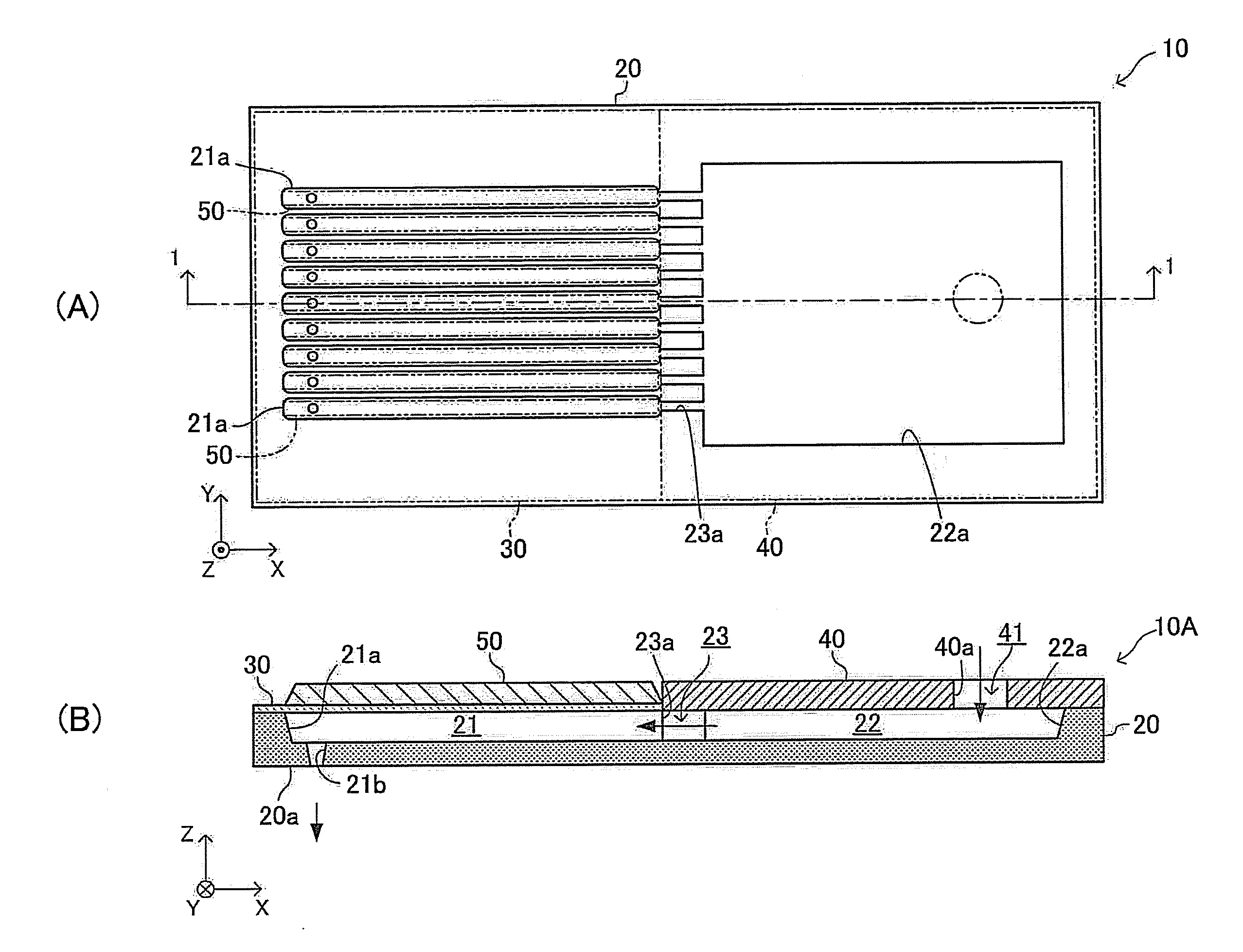
[0093]In place of “removing the remnant membrane RF (forming the through holes H) by the laser processing” in the head-body-before-fired forming step included in the manufacturing method described above, the remnant membrane RF may be removed by a precision polishing after the compact-after-dried 110 is fired. That is, the remnant membrane RF may be removed by a polishing processing after the compact 110 is fired. This enables to precisely adjust a diameter of each of the tip portion (portion of the opening, droplet discharge opening) of the nozzle sections 21b, and therefore, the nozzle plate (discharge hole tip portion forming member) which is another member (e.g., SUS, or the like) may not need to be used.

second modified example

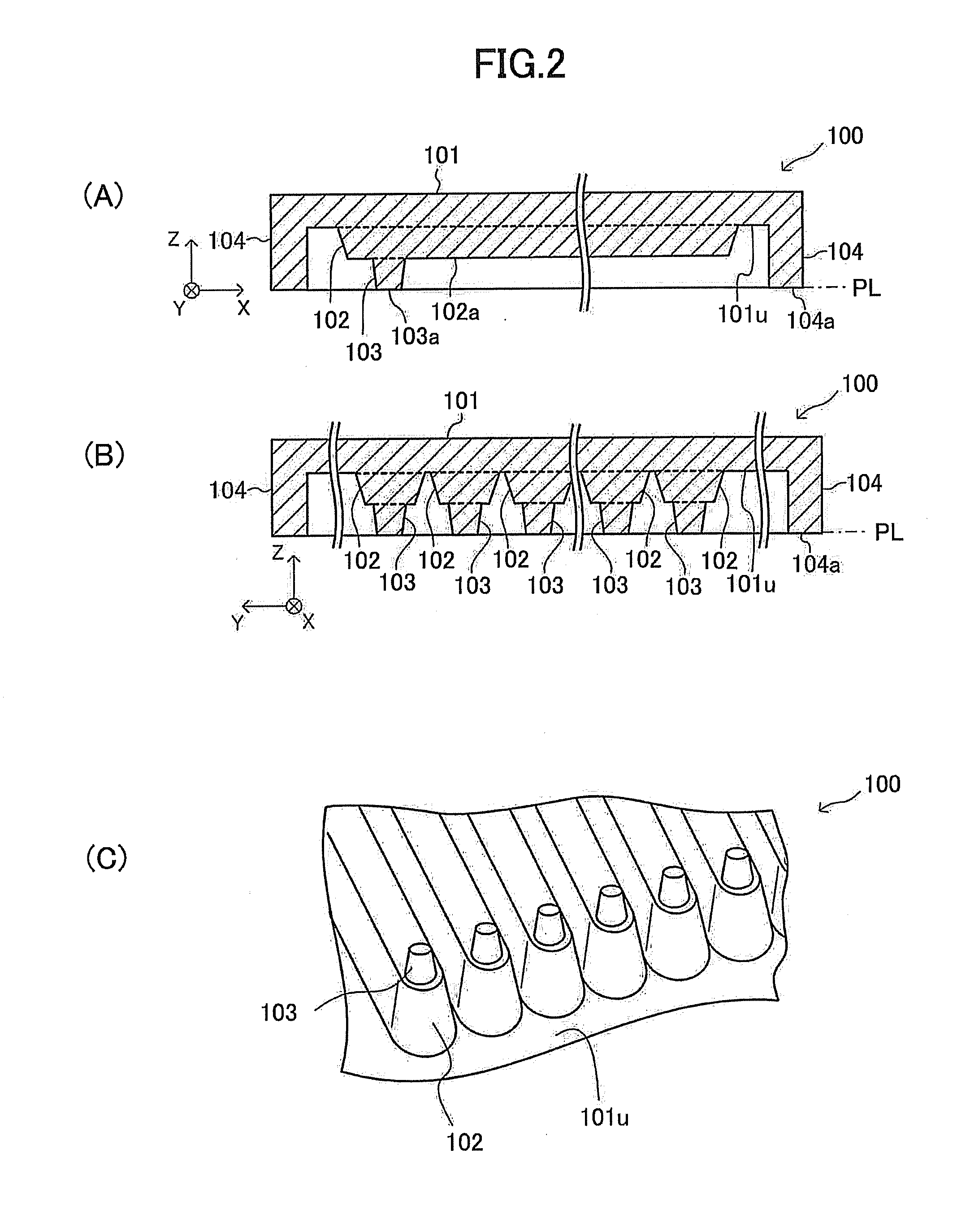
[0094]In place of “removing the remnant membrane RF (forming the through holes H) by the laser processing” in the head-body-before-fired forming step included in the manufacturing method described above, the remnant membrane RF may be removed (eliminated) by a polishing as shown in FIG. 9, after the slurry SL is dried and solidified, and therefore, the compact-after-dried 110 is formed between “the mold 100 and the porous plate 120” (refer to FIG. 4), and before the mold 100 is released from the compact-after-dried 110 (i.e., before demolding). That is, the compact-after-dried 110 may be polished while the compact-after-dried 110 is maintained (held) in the mold 100 to form the through holes H (refer to FIG. 10).

[0095]More specifically, this polishing is performed as follows.

[0096]Firstly, when the compact-after-dried 110 has been formed in the mold 100 as shown in FIG. 4, the compact-after-dried 110 is released / separated from the porous plate 120 while the compact-after-dried 110 i...

third modified example

[0103]In place of “removing the remnant membrane RF (forming the through holes H) by the laser processing” in the head-body-before-fired forming step included in the manufacturing method described above, the remnant membrane RF may be removed (through holes H are formed) by a “special blast processing using elastic grains (described later)” after the compact-after-dried 110 is fired, to thereby complete the nozzle sections 21b.

[0104]More specifically, in the third modified example, “the ceramic green sheet to be the vibration plate 30 and the ceramic green sheet to be the liquid storage chamber cover member 40” are layered (stacked) on the compact-after-dried 110 from which the remnant membrane RF has not been removed yet, while aligning them in a planar direction. Subsequently, these are joined by a thermal compression bonding, and the thermal compression bonded layered body is fired after it is degreased. As a result, the head body-after-fired 20B (droplet discharge head body-bef...


PUM

PropertyMeasurementUnit
Poreaaaaaaaaaa

Abstract

In the method for manufacturing a droplet discharge head, a mold 100, including a convexity portion having convexities which have the substantially same shape as a liquid chamber including pressure chambers 21 and nozzle sections 21b, is prepared. A slurry SL is filled into the mold 100, and the mold 100 is placed on a porous plate 120. A solvent included in the slurry permeates into fine pores of the porous plate. Accordingly, the slurry is dried, so that a compact-after-dried 110 is formed. Thereafter, a vibration plate, and the like are joined to the compact, and the compact is fired. Further, piezoelectric elements, and the like are formed on the pressure chambers.

Description

FIELD OF THE INVENTION[0001]The present invention relates to a method for manufacturing a droplet discharge head, which discharges a droplet of, for example, a liquid containing DNA, a liquid material, a liquid fuel, and the like.BACK GROUND OF THE INVENTION[0002]Conventionally, a ceramic layered body having in its inside a hollow cavity, which is, for example, a pressure chamber for pressurizing a liquid, has been known. Such a ceramic layered body is used in a wide variety of fields including, for example, an apparatus for producing a DNA chip, an “actuator for injecting a fluid” such as a fuel injection device, an actuator for an ink jet printer, a solid-oxide fuel cell (SOFC), a switching device, a sensor, and so on (refer to Patent document 1).[0003]Generally, such a ceramic layered body is manufactured according to procedures described below.[0004](1) Ceramic green sheets are prepared.[0005](2) A through hole having a predetermined shape is formed in the ceramic green sheet by...

Claims


Application Information

Patent Timeline
IPC IPC(8): B24C1/00
CPCB41J2/1637B41J2/1607
Inventor MASE, ATSUSHITANAKA, HIDEHIKOSHIMIZU, HIDEKI
Owner NGK INSULATORS LTD
Why Eureka
Try Eureka