Power supply, method, and computer program product for supplying electrical power to a load

a power supply and load technology, applied in the direction of process and machine control, magnetic variable regulation, instruments, etc., can solve the problem of unlimited voltage rise, reduce the number of direct current voltage supplies, and simplify the design of modulators and pulses.

Inactive Publication Date: 2012-01-12
KONINKLIJKE PHILIPS ELECTRONICS NV
View PDF7 Cites 29 Cited by
  • Summary
  • Abstract
  • Description
  • Claims
  • Application Information

AI Technical Summary

Benefits of technology

[0007]Embodiments of the invention address this previously mentioned problem by replacing one or more of the expensive direct current power supplies with a “floating capacitor.” The charge on the capacitor is able to supply the current necessary for operation of the full bridge circuit. By controlling the modulation of the switches within the bridge circuit, the level of charge on the capacitor can be controlled and it is possible to operate embodiments of the invention continuously. The elimination of direct current power supplies reduces the manufacturing cost of the power supply.
[0032]In another embodiment the load has an inductance. The modulator is adapted for modulating the first switching means and the second switching means such that the capacitors are charged or discharged using electrical energy stored in the load. This is advantageous because it reduces the number of direct current voltage supplies needed, and it also reduces energy consumption by re-using energy stored within the inductance of the load.

Problems solved by technology

Closing both switches is prohibited as this would create a short circuit across the voltage source and thereby possibly cause unlimited current flow; opening both switches would obstruct the current from the current source on the right to flow, possibly causing unlimited voltage rise.

Method used


Image

  • Power supply, method, and computer program product for supplying electrical power to a load
  • Power supply, method, and computer program product for supplying electrical power to a load
  • Power supply, method, and computer program product for supplying electrical power to a load

Examples


Embodiment Construction

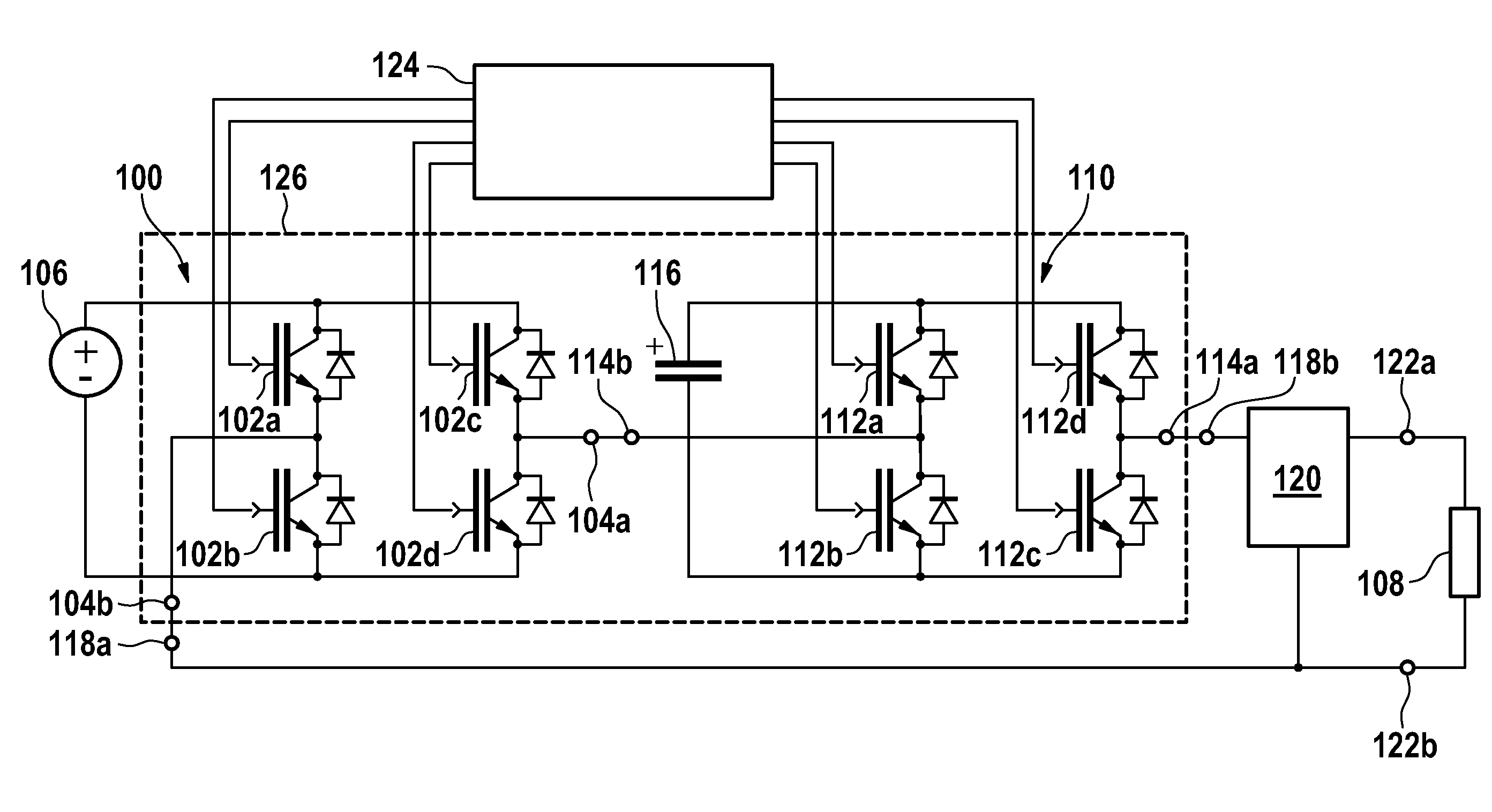
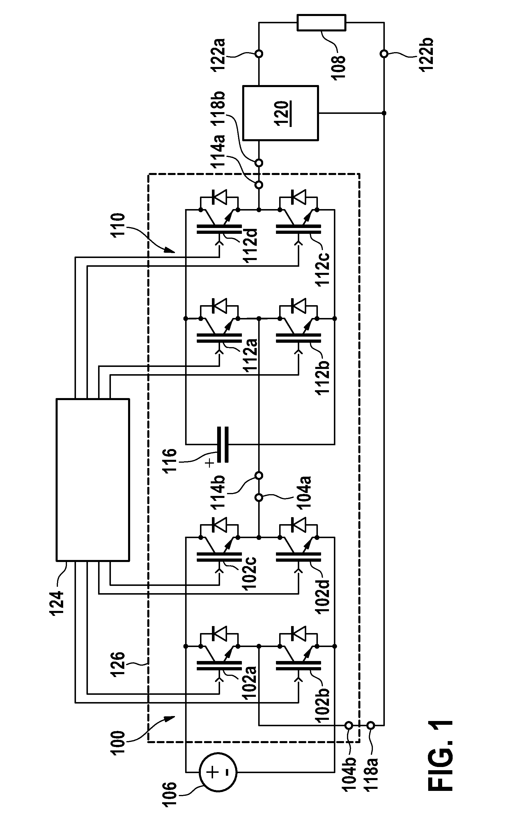
[0062]FIG. 1 shows an embodiment of a power supply according to the invention. The power supply in this embodiment has a single powered full bridge circuit 100 and a single floating full bridge circuit 110. The full bridge circuit 100 comprises a first switching means 102a, 102b, 102c, 102d. The first switching means in this embodiment is constructed using insulated gate bipolar transistors (IGBT) with antiparallel diodes. Each full bridge circuit and floating full bridge circuit is constructed from two phase legs. In the powered full bridge circuit 100 the first phase leg comprises element 102a and element 102b. The second phase leg comprises element 102c and element 102d. Elements 102a and 102b are switched in conjunction and elements 102c and 102d are switched in conjunction. Only one of the switches in a phase leg is switched on at any given time. For instance, if 102a and 102b were both switched on at the same time then the DC power supply 106 would be shorted. Elements 102a an...


PUM


Abstract

A power supply adapted for supplying electrical power to a load (108), the power supply comprising: at least one powered full bridge circuit (100), wherein the powered full bridge circuit is adapted for being powered by a direct current voltage supply(106), wherein the full bridge circuit(100) comprises a first output connection (104a), and a first switching means (102a-102d) for controlling the application of electrical power to the output connection, at least one floating full bridge circuit (110), wherein each floating full bridge circuit comprises a capacitor (116) adapted for powering the floating full bridge circuit (110), wherein each floating full bridge circuit comprises a second output connection (114b), a second switching means (112a-112d) for controlling the application of electrical power to the output connection, a stack of bridge circuits (100, 110) comprising the at least one powered full bridge circuit and the at least one floating full bridge circuit, wherein the second output convection (114b) and first output connection (104a) are connected in series, wherein the stack has a third output connection (114a), a passive filter(120) for averaging the voltage across the third output connection (114a) and connected to the third output connection, a load connector (122a) adapted for connecting the passive filter (120) to the load(108), a modulator (124) adapted for modulating the first switching means and the second switching means such that the charging or discharging of the capacitor (116) is controlled while electrical power is being supplied to or extracted from the load (108).

Description

FIELD OF THE INVENTION[0001]The invention relates to the design and control of pulse width modulated power supplies.BACKGROUND OF THE INVENTION[0002]In Magnetic Resonance Imaging (MRI), three gradient amplifiers and three associated magnetic field gradient coils are typically used to provide 3-dimensional spatial encoding of atomic spins located in a magnetic field.[0003]These gradient amplifiers are typically characterized by high peak power (several 100 kW up to 2 MW for present-day specimens) and high precision of the generated current waveforms. Circuits consisting of series-connected full bridges using pulse-width modulation (PWM) have been used to construct gradient amplifiers.[0004]This circuit topology is known under several names, such as “stacked H-bridges”, “cascaded H-bridges”, or “cascaded multicell converter”. A severe disadvantage of the circuit is that every bridge needs an individual, floating power supply that is well-isolated against both low frequencies and high ...

Claims


Application Information

Patent Timeline
Patent Type & Authority Applications(United States)
IPC IPC(8): H02M3/07G01R33/28
CPCH02M7/483G01R33/3852
Inventor HUISMAN, HENDRIK
Owner KONINKLIJKE PHILIPS ELECTRONICS NV
Why Eureka
Try Eureka