Liquid ejecting apparatus and control method

a technology of liquid ejecting apparatus and control method, which is applied in the direction of printing, other printing apparatus, etc., can solve the problems of increased size deterioration of print quality, and ambient temperature, and achieve the effect of suppressing the increase in size and cost of liquid ejecting head

Inactive Publication Date: 2012-01-12
SEIKO EPSON CORP
View PDF2 Cites 25 Cited by
  • Summary
  • Abstract
  • Description
  • Claims
  • Application Information

AI Technical Summary

Benefits of technology

[0018]In this aspect, since the temperature of the liquid droplet discharged from the liquid ejecting head is detected, a temperature sensor or the like does not need to be provided in a flow path of the liquid ejecting head, and a temperature sensor does not need to be provided in each of the liquid ejecting heads, thereby suppressing increases in the size and costs of the liquid ejecting heads. Since the temperature detection unit detects the temperature of the actually discharged liquid droplets, the driving signal can be corrected to be optimal to the actual liquid temperature, and therefore discharge characteristics of the discharged liquid droplets can be uniformized regardless of temperature changes.

Problems solved by technology

However, measurement of the temperature of liquid is performed by measuring an ambient temperature (atmospheric temperature) of the liquid ejecting head using a sensor, so that an error between the temperature of the liquid inside the pressure generation chamber immediately before being discharged from the liquid ejecting head and the ambient temperature occurs.
Therefore, even though the driving signal is corrected on the basis of the ambient temperature, the driving signal cannot be corrected to be optimal to the actual liquid viscosity, and the discharge characteristics are degraded, so that there is a problem in that print quality is deteriorated.
However, it is difficult to provide the temperature sensor inside the flow path of the pressure generation chamber or the like due to an increase in the density of the liquid ejecting head and a reduction in size thereof, and there is a problem in that as the temperature sensor is provided, the size of the liquid ejecting head is increased, resulting in an increase in costs.
However, there are problems in that an error occurs between the temperature of the liquid immediately before being discharged and the temperature of the liquid in the liquid chamber or the liquid storage unit on the upstream side thereof, and the driving signal cannot be corrected to be optimal to the viscosity of the actually discharged liquid, resulting in degradation of the discharge characteristics and deterioration of print quality.
In addition, these problems are not limited to only the ink jet recording apparatus but also exist in liquid ejecting apparatuses that eject liquids other than ink.

Method used


Image

  • Liquid ejecting apparatus and control method
  • Liquid ejecting apparatus and control method
  • Liquid ejecting apparatus and control method

Examples


first embodiment

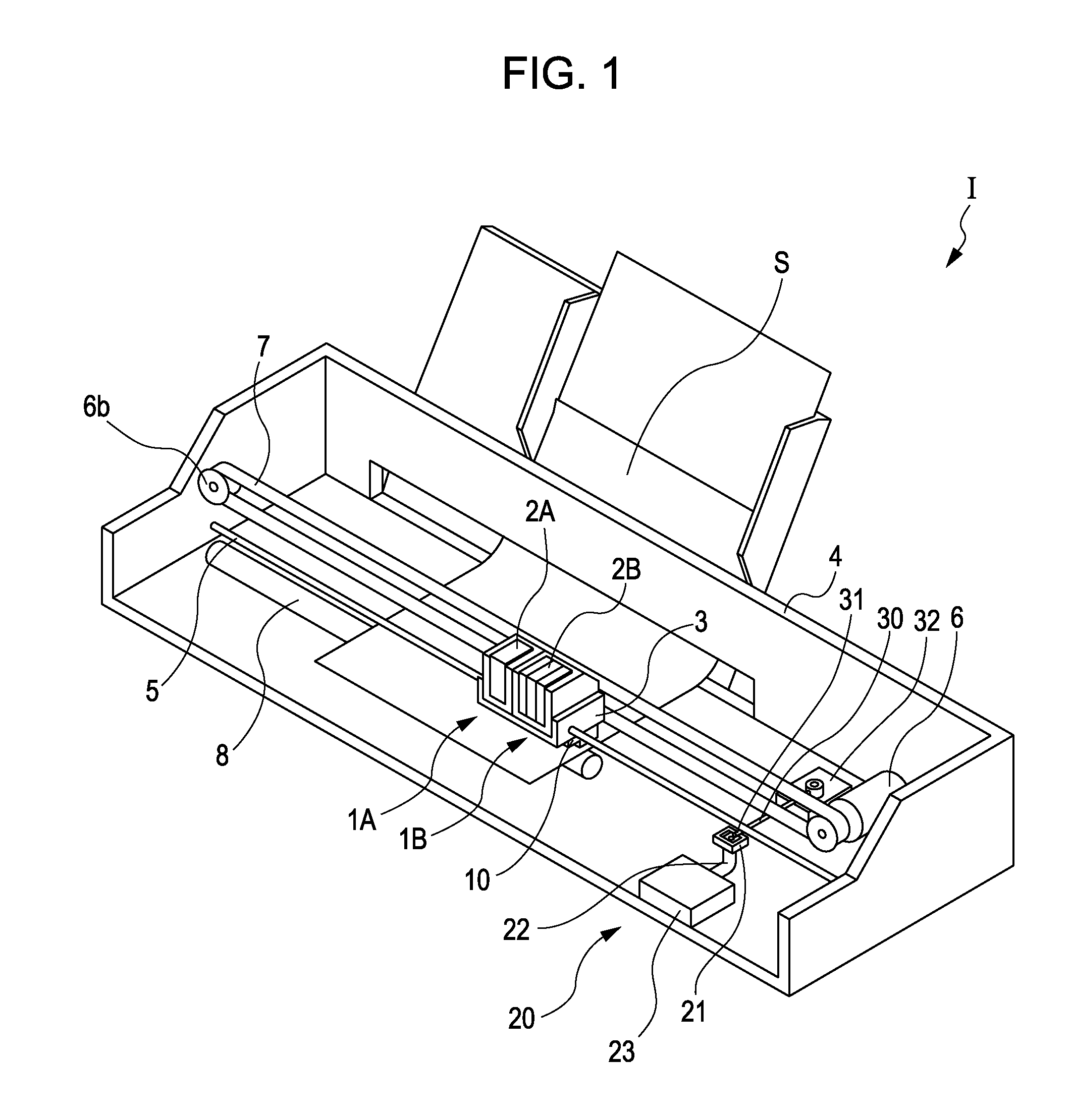
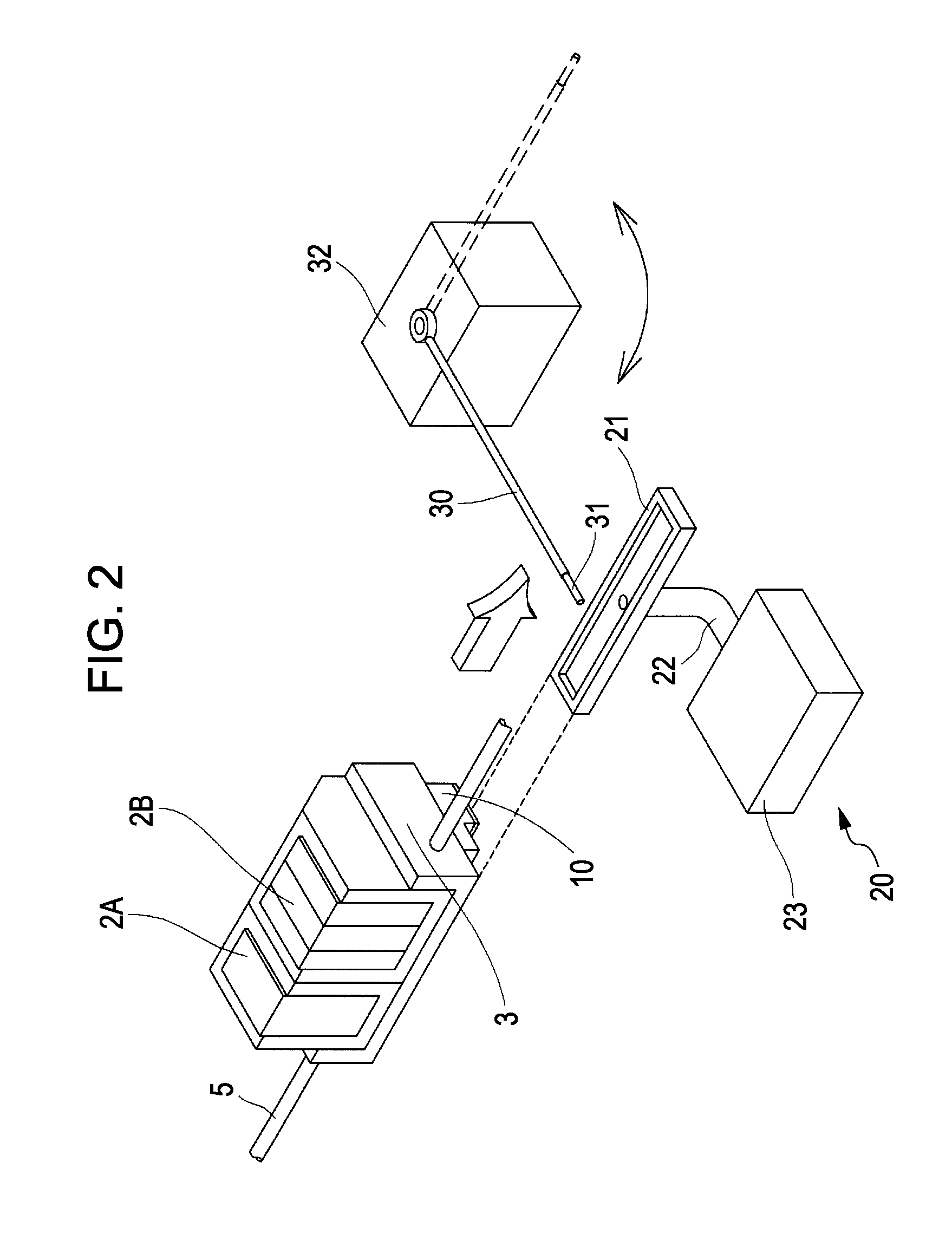
[0031]FIG. 1 is a schematic perspective view showing an ink jet recording apparatus which is an example of a liquid ejecting apparatus according to a first embodiment of the invention, and FIG. 2 is a perspective view of the main part of the ink jet recording apparatus.

[0032]As shown in FIG. 1, the ink jet recording apparatus I has head units 1A and 1B each of which includes an ink jet recording head 10. The ink jet recording heads 10 are provided with cartridges 2A and 2B that constitute an ink supply unit and are detachable, and a carriage 3 in which the head units 1A and 1B are mounted is provided on a carriage shaft 5 mounted in an apparatus body 4 so as to be movable in a main scanning direction which is the axial direction. The head units 1A and 1B discharge, for example, a black ink composition and a color ink composition, respectively.

[0033]In addition, as the driving force of a driving motor 6 is transmitted to the carriage 3 via a plurality of gears (not shown) and a timin...


PUM


Abstract

A liquid ejecting apparatus includes: a liquid ejecting head that includes nozzle openings through which liquid is ejected and pressure generation units that cause changes in pressure of the liquid inside pressure generation chambers communicating with the nozzle openings; a control unit that supplies a driving signal for causing the liquid ejecting head to eject the liquid, to the pressure generation units, and controls ejection of the liquid by the liquid ejecting head; and a temperature detection unit that detects a temperature of a contact portion with which the liquid ejected by the liquid ejecting head comes in contact, wherein the control unit corrects the driving signal on the basis of the temperature information detected by the temperature detection unit.

Description

BACKGROUND[0001]1. Technical Field[0002]The present invention relates to a liquid ejecting apparatus including a liquid ejecting head that ejects liquid and a control method, and more particularly, to an ink jet recording apparatus including an ink jet recording head that discharges ink as liquid and a control method.[0003]2. Related Art[0004]A liquid ejecting apparatus represented by an ink jet recording apparatus such as an ink jet printer or a plotter has a liquid ejecting head capable of discharging liquid from a liquid storage unit such as a cartridge or a tank that stores the liquid as liquid droplets.[0005]Here, the liquid ejecting head includes pressure generation chambers that communicate with nozzle openings and pressure generation units that cause changes in the pressure of the liquid inside the pressure generation chambers to discharge liquid droplets from the nozzle openings. In addition, as the pressure generation unit mounted in the liquid ejecting head, for example, ...

Claims


Application Information

Patent Timeline
Patent Type & Authority Applications(United States)
IPC IPC(8): B41J29/38
CPCB41J2/04553B41J2/04563B41J2/04581B41J29/38B41J2/0459B41J2/04591B41J2/04588
Inventor ZHANG, JUNHUA
Owner SEIKO EPSON CORP
Why Eureka
Try Eureka