Resolver signal converter and resolver signal conversion method

a converter and resolver technology, applied in the direction of code conversion, program control, instruments, etc., can solve the problems of affecting the operation of the rd converter by noise, the angle error caused in the digital angle output of the rd converter, and the frequency dependence of arithmetic processing. , to achieve the effect of reducing the influence, reducing the detection angle errors of the resolver, and eliminating the frequency dependence of arithmetic processing

Active Publication Date: 2012-01-12
KAWASAKI HEAVY IND LTD
View PDF5 Cites 25 Cited by
  • Summary
  • Abstract
  • Description
  • Claims
  • Application Information

AI Technical Summary

Benefits of technology

[0020]The present invention eliminates frequency dependence of arithmetic processing, and reduces an influence, on an input resolver signal, of disturbance noise such as noise caused due to a magnetic field generated by a motor and switching noise caused due to PWM driving. This makes it possible to reduce detection angle errors of a resolver.

Problems solved by technology

A resolver included in such a PWM-driven motor is affected by switching noise.
If such disturbance noise is superimposed on a resolver signal that is inputted to the RD converter, then the operation of the RD converter is affected by the noise.
Accordingly, digital angle outputs from the RD converter contain angle errors caused by the disturbance noise.

Method used


Image

  • Resolver signal converter and resolver signal conversion method
  • Resolver signal converter and resolver signal conversion method
  • Resolver signal converter and resolver signal conversion method

Examples


Embodiment Construction

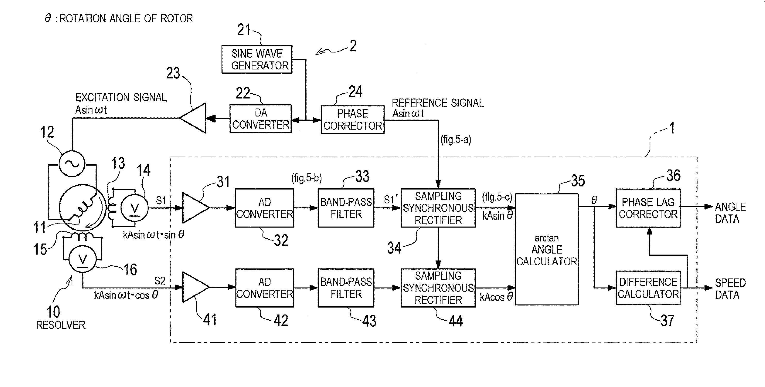
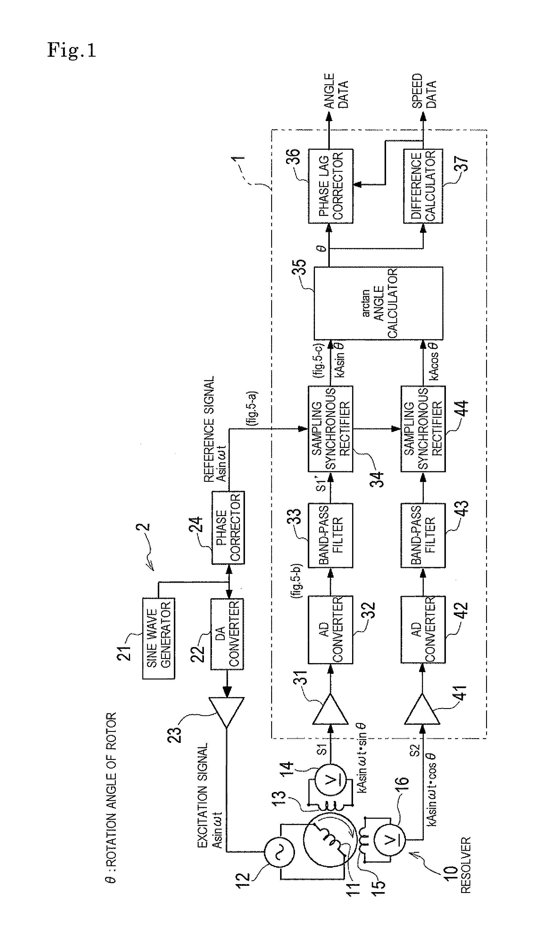
[0027]Hereinafter, an embodiment of the present invention is described in detail with reference to the accompanying drawings. A resolver signal converter according to the embodiment of the present invention is configured as a resolver-digital converter (hereinafter, referred to as an “RD converter 1”). FIG. 1 shows a configuration of the RD converter 1, and shows the RD converter 1, a resolver 10, and an excitation signal generator 2, collectively as an angle detection device.

[0028]The resolver 10 is disposed near the winding of a motor (not shown). The resolver 10 includes: an excitation coil 11 provided at the rotor of the motor; and a first detection coil 13 and a second detection coil 15 which are provided at the stator of the motor. The excitation coil 11 is supplied with an AC voltage from an AC power supply 12, which AC voltage is based on an excitation signal generated by the excitation signal generator 2. The first detection coil 13 and the second detection coil 15 are posi...


PUM


Abstract

A resolver signal converter and a resolver signal conversion method amplify and perform analogue-digital conversion on a sine wave output from a resolver; thereafter, among frequency components of the sine wave output, pass and thereby extract a predetermined bandwidth of which the center frequency is the frequency of an excitation signal, by means of a band-pass filter; sample the sine wave output while synchronizing the sine wave output with a reference signal which is based on the excitation signal; and generate a detection angle signal sine value from the sampled signal. Similarly, a detection angle signal cosine value is generated from a cosine wave output from the resolver. A detection angle is calculated based on the detection angle signal sine value and the detection angle signal cosine value. Accordingly, an influence, on an input resolver signal, of disturbance noise such as noise caused due to a magnetic field generated by a motor and switching noise caused due to PWM driving, is eliminated, and frequency dependence of arithmetic processing is eliminated. As a result, detection angle errors are reduced.

Description

TECHNICAL FIELD [0001]The present invention relates to a resolver signal converter and a resolver signal conversion method for converting detection angles of two-phase resolver signals outputted from a resolver which is configured to detect a rotation angle of a motor or the like, into a digital output angle.BACKGROUND ART [0002]Conventionally, resolvers are used for detecting a rotation angle of a motor or the like. Such a resolver includes an excitation coil and detection coils. When an alternate current is supplied to the excitation coil, an AC voltage is generated at each detection coil in accordance with a relative angle between a stator and a rotor. These AC voltages are detected by voltmeters which are connected to the respective detection coils, and are then outputted to a resolver-digital converter (RD converter). The RD converter converts detection angles contained in respective resolver signals inputted thereto, into digital angle data, and outputs the digital angle data....

Claims


Application Information

Patent Timeline
Patent Type & Authority Applications(United States)
IPC IPC(8): G06F15/00
CPCG05B2219/37481G08C19/46H03M1/645G01D5/2073H03M1/0617H03M2201/843G01D5/20G01D5/244
Inventor YAMADA, MASAHIRO
Owner KAWASAKI HEAVY IND LTD
Why Eureka
Try Eureka