Magnetic memory

a magnetic memory and memory technology, applied in the field of magnetic memory, can solve the problems of increasing power consumption and destroying lines, and achieve the effect of reducing curren

Inactive Publication Date: 2012-01-19
HITACHI LTD
View PDF2 Cites 11 Cited by
  • Summary
  • Abstract
  • Description
  • Claims
  • Application Information

AI Technical Summary

Benefits of technology

[0024]According to the present invention, it is possible to provide a magnetic random access memory adopting spin torque magnetization reversal in which a laminated ferrimagnetic recording layer is applied, the laminated ferrimagnetic recording layer being thermally stable when reading and capable of reducing a current when writing.

Problems solved by technology

However, even in the MRAM, there is pointed out a problem that the magnitude of the magnetic field required for the magnetization reversal is increased when the size of the TMR element is reduced in order to achieve higher capacity, so that it is necessary to feed a large amount of the current through the metal lines which may incur an increase in power consumption and lead to destruction of the lines eventually.

Method used


Image

  • Magnetic memory
  • Magnetic memory
  • Magnetic memory

Examples


first embodiment

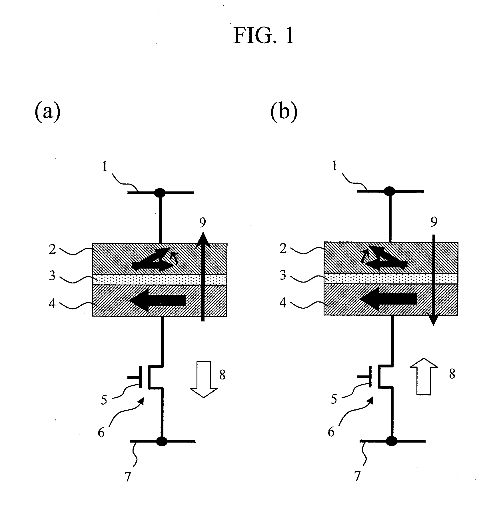
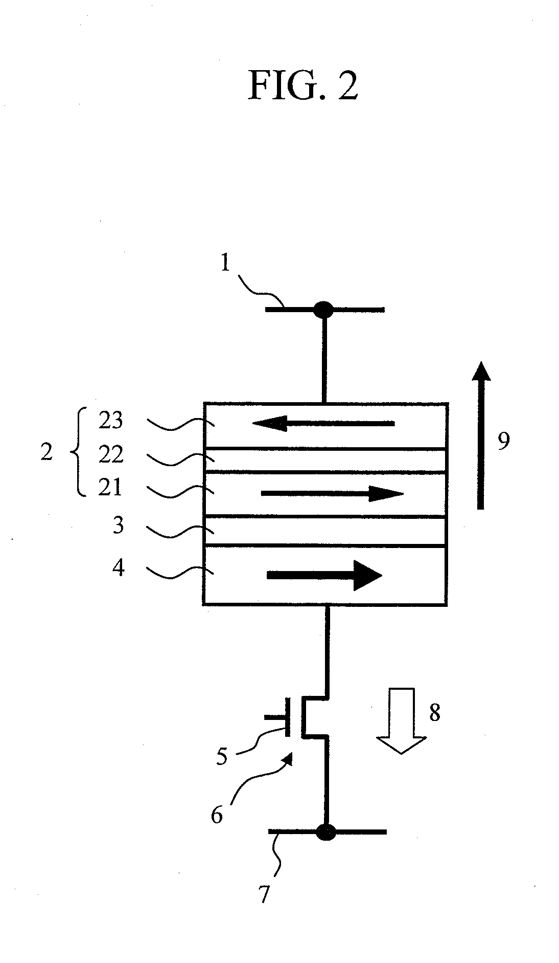
[0076]The exchange coupling magnetic field is a magnetic field which attempts to maintain directions of the magnetizations of the two ferromagnetic films 21 and 23, which are constituent members of the laminated ferrimagnetic recording layer 2 in an antiparallel state. It is necessary to set a film thickness of the nonmagnetic film 22 interposed between the ferromagnetic films 21 and 23 to an optimum value in order to increase the exchange coupling magnetic field. This film thickness varies depending on the material or the composition of the ferromagnetic films, the material of the nonmagnetic layer, and a heat treatment temperature after film formation. In the following, a case of using CoxFeyBz as the material of the ferromagnetic layers 21 and 23 and using Ru as the material of the nonmagnetic layer 22 will be described. In particular, a CoFe alloy having the z value equal to about 20% can achieve a high TMR ratio when MgO is used as the material of a nonmagnetic barrier layer 3....

second embodiment

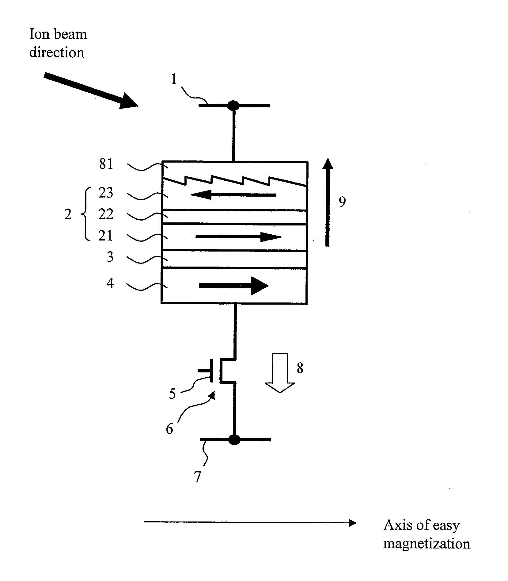
[0092]An embodiment of adding a texture to the upper ferromagnetic layer 23 of the laminated ferrimagnetic recording layer will be described. FIG. 8 shows the example in which the ferromagnetic layer 23 is provided with the texture in the direction of the axis of easy magnetization by use of an appropriate means and a cap layer 81 made of a metallic material is provided thereon. The direction of a periodic structure of texture grooves is substantially perpendicular to the direction of the axis of easy magnetization of the ferromagnetic layer 23.

[0093]With the configuration described above, an antimagnetic field attributable to this microstructure has a function to prevent rotation of the magnetization in the direction perpendicular to the direction of the axis of easy magnetization (i.e., in the direction of the axis of hard magnetization), thereby increasing magnetic anisotropy. As for the material of the cap layer, a material having a high melting point and a low resistance such a...

third embodiment

[0101]Next, a description will be given of a method of providing an additional magnetic layer on the TMR element and setting two magnetization angles of the laminated ferrimagnetic free layer so as to satisfy q1˜q2+180 by utilizing a leakage magnetic field from the additional magnetic layer.

[0102]In FIG. 11, reference numeral 111 denotes a cap layer, reference numeral 112 denotes an additional magnetic layer, reference numeral 113 denotes a conductive intermediate layer, reference numeral 116 denotes a current flowing through the bit line 1, reference numeral 115 denotes a magnetic field generated by the current through the bit line 1, and reference numeral 114 denotes a magnetic field generated by the magnetization of the additional magnetic layer 112. Other configurations are the same as those in FIG. 6. Although a soft magnetic material such as NiFe is desirable as the material of the additional magnetic layer 112, an alloy of any of Co, Ne, and Fe is used in a broader sense. As ...


PUM


Abstract

Provided is a magnetic random access memory to which spin torque magnetization reversal is applied, the magnetic random access memory being thermal stable in a reading operation and also being capable of reducing a current in a wiring operation. A magnetoresistive effect element formed by sequentially stacking a fixed layer, a nonmagnetic barrier layer, and a recording layer is used as a memory element. The recording layer adopts a laminated ferrimagnetic structure. The magnetic memory satisfies the expression Ms2(t/w)>|Jex|>(2kBTΔ)/S, in which kB is a Boltzmann constant, T is an operating temperature of the magnetic memory, S is an area parallel to a film surface of the magnetoresistive effect element, t and Ms are respectively a film thickness and a saturated magnetization of the ferromagnetic layer having a smaller film thickness among two ferromagnetic layers which are constituent members of the laminated ferrimagnetic structure, w is a length of a short side of the recording layer, Δ is a thermal stability index of the magnetic memory, and Jex is exchange coupling energy acting between the two ferromagnetic layers of the recording layer.

Description

TECHNICAL FIELD[0001]The present invention relates to a magnetic memory and a magnetic random access memory to which spin torque magnetization reversal is applied.BACKGROUND ART[0002]In recent years, a magnetic random access memory (MRAM) having a potential to replace a conventional dynamic random access memory (DRAM) has been drawing attention. As described in U.S. Pat. No. 5,734,605, for example, a conventional MRAM adopts a recording method by reversing a magnetization of one end of a tunnel magnetoresistive effect (TMR) element by use of a synthetic magnetic field created by a current flowing through two metal lines provided in mutually orthogonal directions above and below the TMR element. Here, the tunnel magnetoresistive effect (TMR) element has a multilayer structure of a magnetic film / a nonmagnetic insulating film / a magnetic film. However, even in the MRAM, there is pointed out a problem that the magnitude of the magnetic field required for the magnetization reversal is inc...

Claims


Application Information

Patent Timeline
Patent Type & Authority Applications(United States)
IPC IPC(8): H01L29/82
CPCH01L43/08G11C11/16G11C11/161G11C11/1675H10N50/10H01L27/105H01L29/82H10B99/00
Inventor ITO, KENCHIHAYAKAWA, JUNMIURA, KATSUYAYAMAMOTO, HIROYUKI
Owner HITACHI LTD
Why Eureka
Try Eureka