Method of manufacturing sparkplugs

a manufacturing method and technology of spark plugs, applied in the manufacture of spark plugs, spark plugs, electrical equipment, etc., can solve the problems of deterioration of spark endurance, separation of noble metal tips, etc., and achieve the effect of improving welding strength

Active Publication Date: 2012-01-19
NGK SPARK PLUG CO LTD
View PDF4 Cites 9 Cited by
  • Summary
  • Abstract
  • Description
  • Claims
  • Application Information

AI Technical Summary

Benefits of technology

[0006]The present invention has been conceived to solve the conventional problems mentioned above, and an object of the invention is to provide a technique for improving welding strength between a ground electrode and a noble metal tip.MEANS FOR SOLVING THE PROBLEMS
[0009]According to the method of manufacturing a spark plug of application example 1, the area of such a portion of the fusion zone that falls within the boundary between the ground electrode and the noble metal tip is increased. Therefore, the method can manufacture a spark plug having an enhanced welding strength between the ground electrode and the noble metal tip. Further, since the shape of the fusion zone is substantially symmetrical with respect to the centerline, the difference in thermal stress between the left side and the right side of the centerline can be rendered substantially zero. Therefore, deterioration in welding strength caused by the differential thermal stress can be restrained.Application Example 2

Problems solved by technology

This method can increase the welding strength between the ground electrode and the noble metal tip, but involves a problem of a deterioration in spark endurance, since the discharge surface of the noble metal tip contains components of a ground electrode base metal as a result of fusion.
This method, however, involves the following problem: the welding strength between the ground electrode and a central portion of the noble metal tip is weak, and cracking may be generated in the noble metal tip or a fusion zone, potentially resulting in separation of the noble metal tip.
This method, however, involves the following problem: since the layer of a fusion zone at the interface between the ground electrode and the noble metal tip is thin, welding strength fails to cope with such a severe working environment of a spark plug that is increased in temperature in association with recent tendency toward higher engine outputs, potentially resulting in separation of the noble metal tip.

Method used


Image

  • Method of manufacturing sparkplugs
  • Method of manufacturing sparkplugs
  • Method of manufacturing sparkplugs

Examples


first embodiment

A. First Embodiment

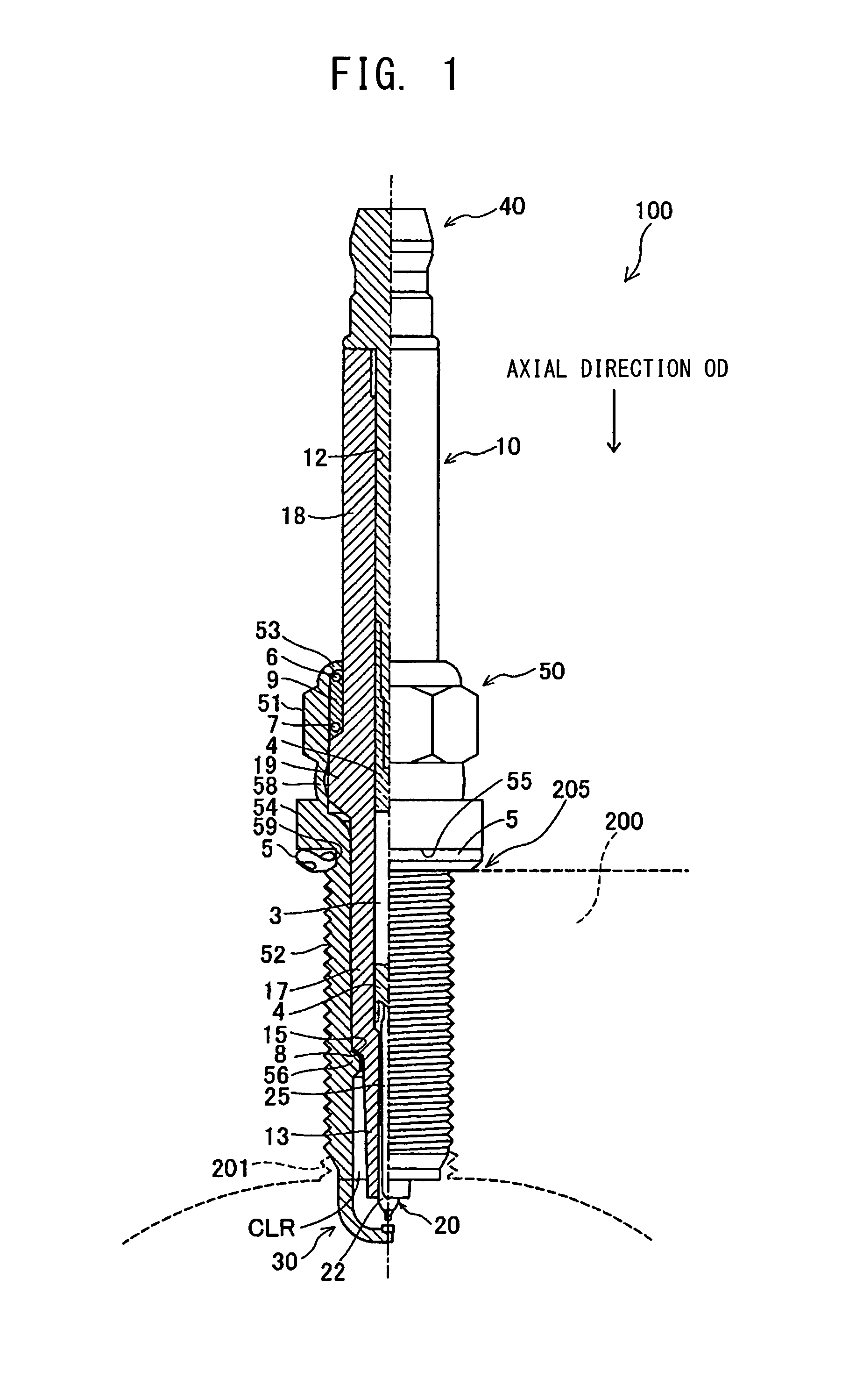
[0044]FIG. 1 is a partially sectional view showing a spark plug 100 according to an embodiment of the present invention. In the following description, an axial direction OD of the spark plug 100 in FIG. 1 is referred to as the vertical direction, and the lower side of the spark plug 100 in FIG. 1 is referred to as the front side of the spark plug 100, and the upper side as the rear side.

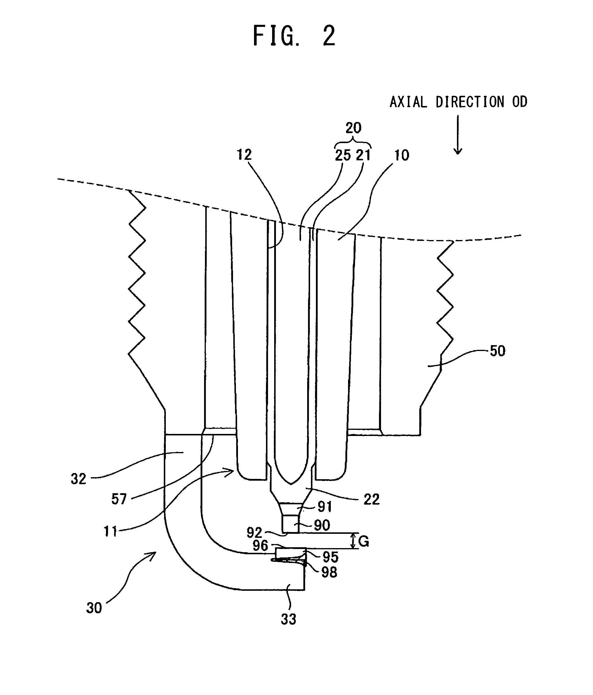
[0045]The spark plug 100 includes a ceramic insulator 10, a metallic shell 50, a center electrode 20, a ground electrode 30, and a metal terminal 40. The center electrode 20 is held while extending in the ceramic insulator 10 in the axial direction OD. The ceramic insulator 10 functions as an insulator. The metallic shell 50 holds the ceramic insulator 10. The metal terminal 40 is provided at a rear end portion of the ceramic insulator 10. The constitution of the center electrode 20 and the ground electrode 30 will be described in detail later with reference to FIG. 2.

[0046]The cer...


PUM


Abstract

A method of manufacturing a spark plug having an insulator, a center electrode, a metallic shell, a ground electrode, and a noble metal tip provided on the ground electrode and having a discharge surface forming a spark discharge gap in cooperation with the center electrode. The method of manufacturing includes a fusion-zone formation step of forming a fusion zone through radiation of a high-energy beam to the boundary between the ground electrode and the noble metal tip.

Description

FIELD OF THE INVENTION[0001]The present invention relates to a method of manufacturing a spark plug.BACKGROUND OF THE INVENTION[0002]Conventionally known methods of joining a noble metal tip to a ground electrode of a spark plug are disclosed in, for example, PCT Application Laid-Open No. 2004-517459 (“Patent Document 1”) and US Patent Application Publication No. 2007 / 0103046 (“Patent Document 2”).[0003]According to the method disclosed in Patent Document 1, a noble metal tip is completely melted and joined to a ground electrode. This method can increase the welding strength between the ground electrode and the noble metal tip, but involves a problem of a deterioration in spark endurance, since the discharge surface of the noble metal tip contains components of a ground electrode base metal as a result of fusion.[0004]Also, according to the method disclosed in Patent Document 2, a peripheral portion of a noble metal tip is melted, thereby joining the noble metal tip to a ground elec...

Claims


Application Information

Patent Timeline
Patent Type & Authority Applications(United States)
IPC IPC(8): H01T21/02
CPCH01T21/02H01T13/38H01T13/20
Inventor NAKAYAMA, KATSUTOSHISAKAYANAGI, NOBUAKI
Owner NGK SPARK PLUG CO LTD
Why Eureka
Try Eureka