[0007]In view of the above, it is desirable to provide a suspension arm unit for vehicle whose fabrication is simpler.
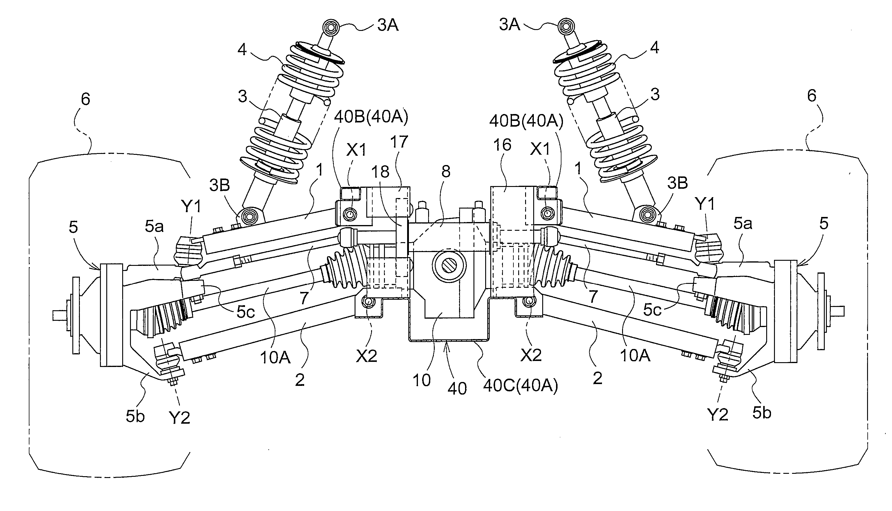
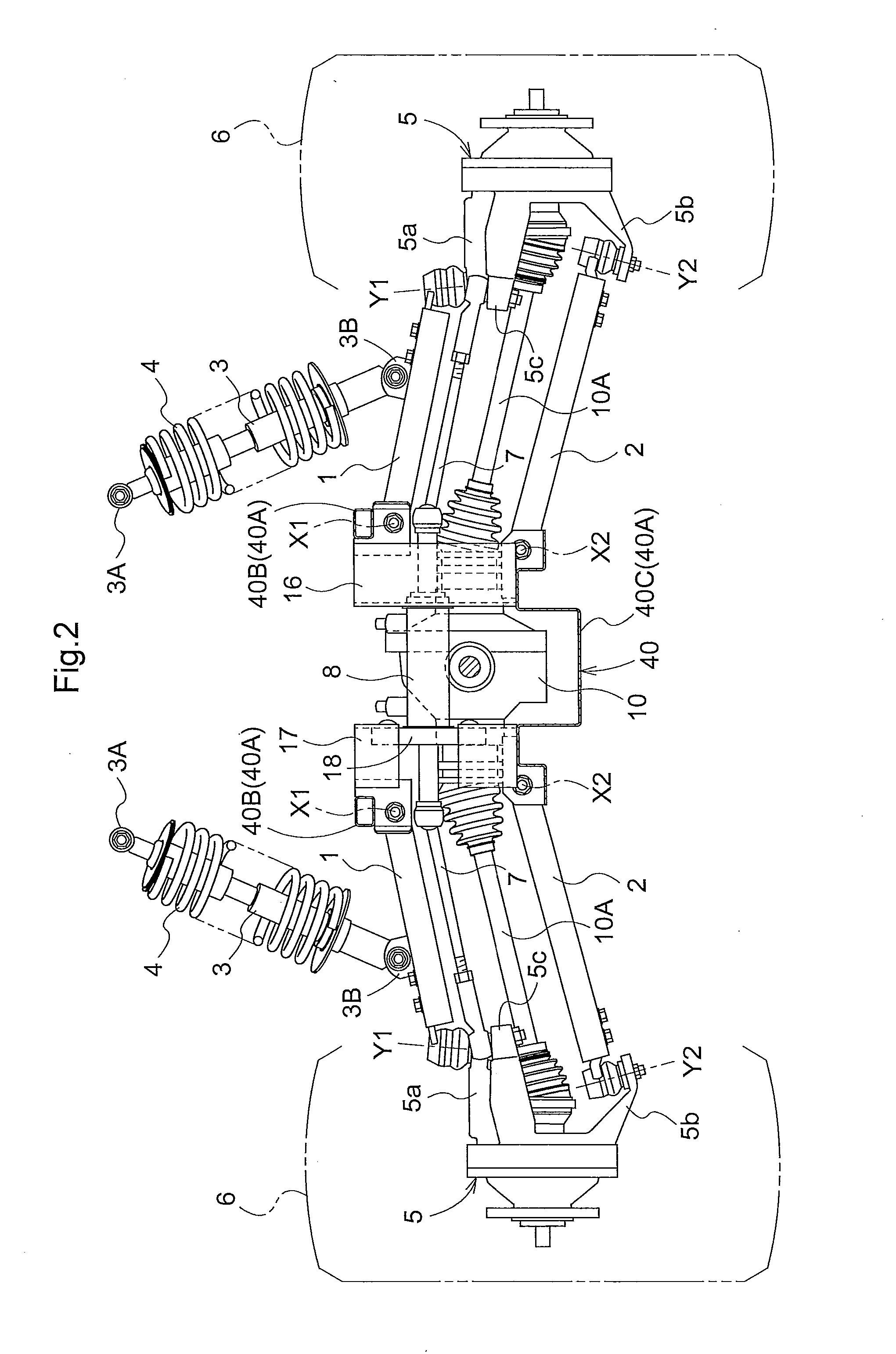
[0009]In the suspension arm of the present invention, the pair of the profile beams each having the U-shaped cross section are arranged in such a manner that the openings (of the U shapes) face each other, and the profile beams become gradually apart from each other from the distal end part to the base end part. With this configuration, by joining the distal end parts of the profile beams together, a suspension arm can be fabricated. Since a structure of the profile beam itself having the U-shaped cross section is simple, and the profile beam can be fabricated by a production method in three plates are welded or by bending
processing on a single sheet
metal using a very general mold and a simple press technique, the production cost can be effectively reduced. In addition, when a design change is required in, for example, the distance between the base end parts, it is relatively easily realized by changing an
assembly angle of the pair of the profile beams. When the base end parts are processed for the purpose of easy
welding of the bush or the like for swingably connecting the arms to the vehicle body, an appropriate shape can be obtained by simple
processing of merely
cutting out an end part of a vertical plate part of the U-shaped cross section into a shape of an arc.
[0011]With this configuration, since the plates forming the profile beams are overlapped in the vertical direction and welded, a
welding operation is simpler, as compared with a method in which end faces of the pair of the profile beams are brought into contact at the same height level and welded. In addition, at a
welding part, high rigidity is obtained due to the overlapped plates. Further, an overlap width in the front-rear direction between the plates can be appropriately adjusted so as to realize a desired finished size of the arm member, the arm member itself is not required to have high dimension accuracy, and consequently the cost can be reduced. Moreover, with this configuration, since an ideal weld surface (
lap joint) is formed of two orthogonal faces including an upper face of a lower plate and an end face of an upper plate at a position where two plates are overlapped, a welding operation becomes very easy, and high
weld strength is easily obtained. Further, in a case where two
parallel plate parts of a U-shape of one of the profile beams is inserted into an opening of a U-shape of the other of the profile beams, the profile beams should have two different sizes (large and small) in the U-shape, while with the present configuration, the pair of the profile beams can be shaped to have exactly the same size.
[0012]In another preferred embodiment of the present invention, each of the profile beams is formed from a
single plate by bending processing. With this configuration, as compared with a configuration in which the profile beam is obtained by a method in which three plates are welded, the profile beam can be fabricated in a shorter time, and higher reliability in strength can be obtained.
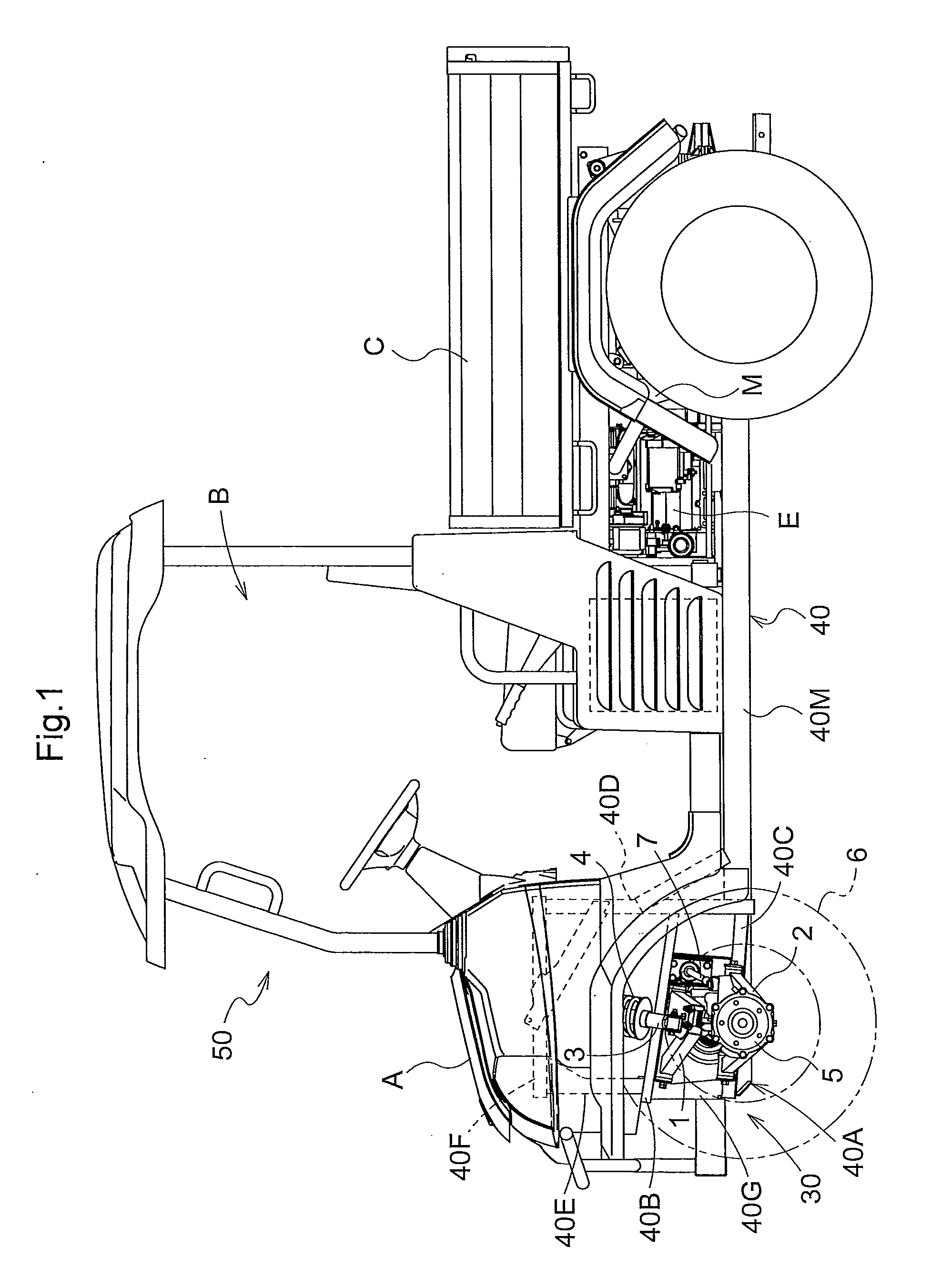
[0013]In other embodiment of the present invention, a maximum length in the front-rear direction of the distal end part of each of the profile beams has at least the front-rear length of a distal end part of the arm. With this configuration, the arm can easily exert satisfactory strength relative to a stress in the front-rear direction of the vehicle. In addition, since the overlap edge of the pair of the profile beams is not in the vicinity of a central portion in the front-rear direction but in the vicinity of the vertical plate part, strength in the vertical direction at a part unified by welding can be easily secured. Moreover, an area for attaching a lower end of
damper for supporting a vehicle
body weight can be easily secured in an upper face of the arm.

