Power grid signal coupler system

a power grid and signal coupler technology, applied in powerline communication systems, transmission, inductances, etc., can solve the problems of large physical dimensions, high supply current draws, and contribute to a substantial reduction of the overall bandwidth of the system

Inactive Publication Date: 2012-01-26
VAVIK GEIR MONSEN
View PDF1 Cites 2 Cited by
  • Summary
  • Abstract
  • Description
  • Claims
  • Application Information

AI Technical Summary

Problems solved by technology

The resulting conversion that takes place within them causes high supply current draws and they tend to be of large physical dimensions.
In addition each repeater contributes to a substantial reduction of the overall bandwidth of the system and always introduces problematic latencies that either excludes or complicates certain modern, time critical telecommunication services.
There are physical limitations as well to which extent technologies within digital repeaters can be developed for large bandwidths.
With known semiconductor types there are physical limits to how much it is possible to reduce current consumption at high processing speeds being limited, amongst other factors, by the lower limit of transistor bias and clock frequencies.
Such concepts are likewise not inexpensive in production as for instance due to their obligation to utilise the newest and most expensive technology available.
Such technologies are therefore likely to be quickly replaced by new generations leading to hi write-off costs.
As a consequence, it is too expensive and impracticable to use a sufficient number of such repeaters for, as an example sustaining signal levels on cables or for wireless coverage in an area where line of sight obstructions are significant.
It has been claimed that analogue repeaters as opposed to digital repeaters accumulate noise.
These are conclusions with substantial flaws in addition to the fact that digital repeater systems will accumulate noise that gradually reduces symbol bandwid...

Method used


Image

  • Power grid signal coupler system
  • Power grid signal coupler system
  • Power grid signal coupler system

Examples


Embodiment Construction

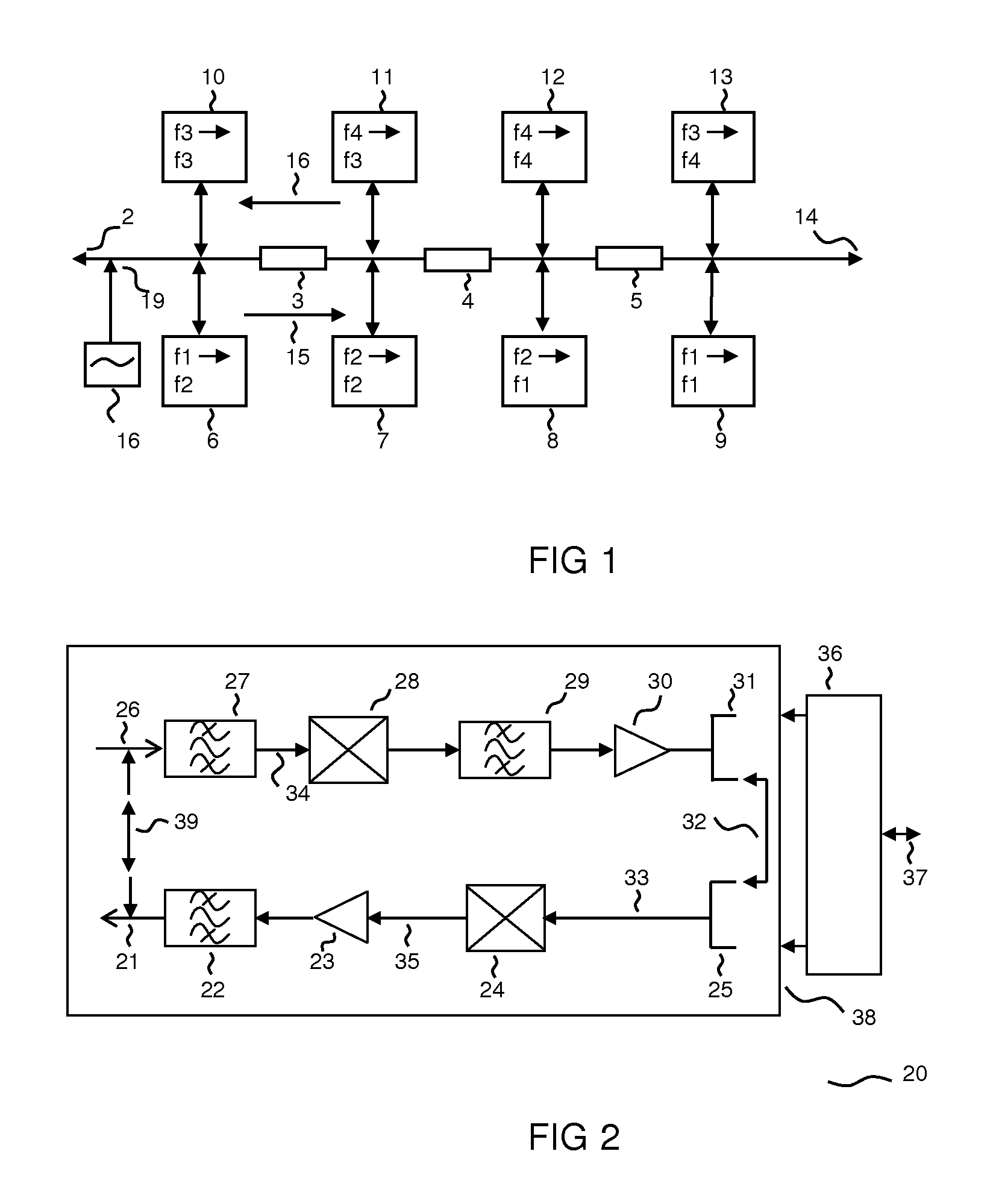
[0033]FIG. 1 illustrates how the invention in a repeater system 1 or a repeater cascade 1 makes use of frequency transposing repeaters where isolation against echo between repeaters is made redundant by the use of three frequency bands, f1, f2, f2 for each information channel, possibly each signal direction in use. The figure shows in more detail how the invention makes use of a repeater cascade 1 with the help of frequency transposing repeaters 6, 8 in combination with repeaters that amplifies within the same channel 7, 9 by applying only two frequency bands, f1 and f2 for on and the same information channel. This is achieved in a symmetrical system by repeater 6 frequency shifting from frequency f1 to f2. The nest repeater 7 repeats the signal within the same frequency band, f2. The next repeater 8 repeats by frequency shifting to f1. Further on the sequence is repeated starting with the subsequent attenuation 5 and repeater 9. In this way echo for example into one repeater 6 from...


PUM


Abstract

The present invention concerns signal coupler systems for power grids, in particular novel methods and apparatus to obtain signal isolation as well as methods for exploiting behavior of existing apparatus.

Description

[0001]The present invention concerns analogue signal repeater system concepts of the general type as explained in the preamble of the appended claim 1, as well as analogue signal repeater as described in appended claim.BACKGROUND[0002]During the last 20 years, analogue, high frequency repeaters in data communication systems have been neglected in favour of digital concepts. Analogue gain may be realised with analogue or digital signal processing methods and are characterised firstly by their full or part transparency. They offer an amplified, analogue representation of the input signal to give a near sustained bandwidth and very low latency even at very large system bandwidths. Digital repeaters are not transparent and are commonly based on just one type of modulation as well as one type of communication protocol, which again is likely to be of proprietary character. The resulting conversion that takes place within them causes high supply current draws and they tend to be of large p...

Claims


Application Information

Patent Timeline
IPC IPC(8): H02J17/00
CPCH04B2203/5483H04B3/544
Inventor VAVIK, GEIR MONSEN
Owner VAVIK GEIR MONSEN
Why Eureka
Try Eureka