Lithium ion battery

a technology ion batteries, applied in the field of lithium ion batteries, can solve problems such as cell unusability

Inactive Publication Date: 2012-01-26
DRITTE PATENTPORTFOLIO BET GMBH & CO KG
View PDF5 Cites 17 Cited by
  • Summary
  • Abstract
  • Description
  • Claims
  • Application Information

AI Technical Summary

Benefits of technology

[0025]In each case, polymers are used which have a glass transition temperature higher than 150° C. The described methods enable polymers with a correspondingly high gla

Problems solved by technology

At higher temperatures, the PEO liquefies, at least locally, to the extent that there

Method used


Image

  • Lithium ion battery
  • Lithium ion battery

Examples


Embodiment Construction

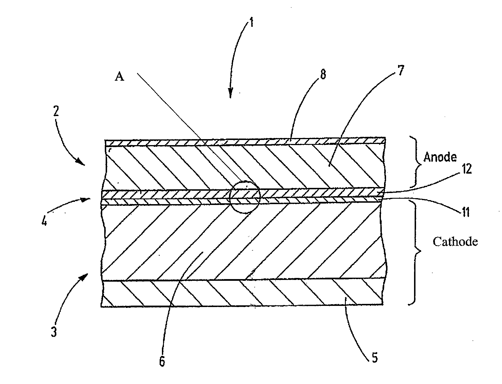
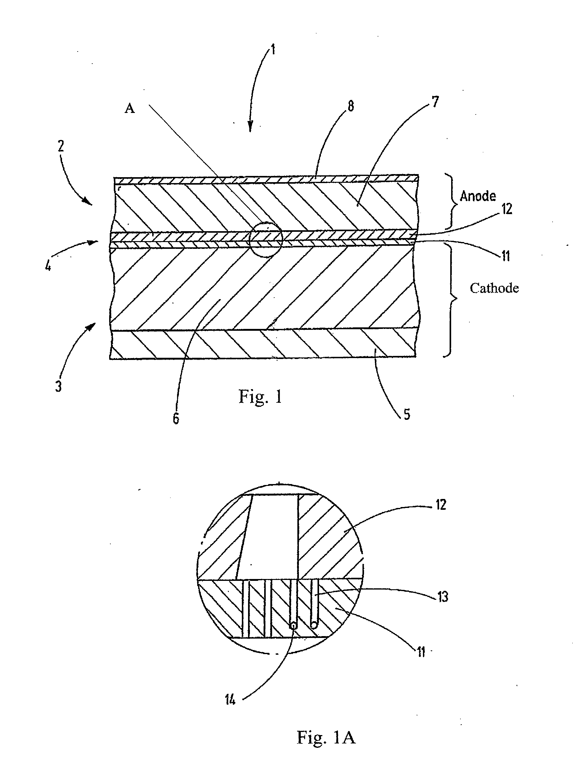
[0032]FIG. 1 shows the schematic structure of a lithium ion battery 1. The lithium ion battery comprises an anode arrangement 2 as well as a cathode arrangement 3, likewise formed as a layer. A membrane structure layer 4 is situated between the anode and the cathode 2, 3, which separates the anode layer 2 from the cathode layer 3 to prevent an electrical short circuit between the two.

[0033]The cathode layer 3 consists of a substrate 5 which is, for example, nickel or an inconel band (stainless steel). This band-shaped substrate 5 supports a polycrystalline layer 6 able to accommodate lithium ions in a crystalline lattice, which one skilled in the art refers to as intercalation. The material for the polycrystalline layer 6 can be selected from among substances such as MnO2, COO2, NiMn, or other substances having similar intercalation properties.

[0034]Known methods are used to deposit the polycrystalline layer 6 on the substrate 5, for example ion beam mixing in which an ion beam bomb...


PUM

PropertyMeasurementUnit
Temperatureaaaaaaaaaa
Thicknessaaaaaaaaaa
Thicknessaaaaaaaaaa

Abstract

A lithium battery comprising an anode and a cathode structure separated from one another by a membrane structure. The membrane structure comprises a layer which is only conductive to lithium ions and which is characterized by the property of having sufficient mechanical stability at temperatures higher than 150° C. to prevent a local short circuit between the anode and the cathode structure.

Description

CROSS-REFERENCE TO RELATED APPLICATIONS[0001]This application is a Section 371 of International Application No. PCT / EP2009 / 063682, filed Oct. 19, 2009, which was published in the German language on Apr. 29, 2010, under[0002]International Publication No. WO 2010 / 046346 A1 and the disclosure of which is incorporated herein by reference.BACKGROUND OF THE INVENTION[0003]Lithium ion batteries essentially have three layers. One of the layers is the cathode layer, another layer is the anode layer, and between those layers is a film or membrane layer to keep the cathode and anode layers separated.[0004]The cathode layer consists of a metallic film and a nanocrystalline layer deposited thereon. The nanocrystalline layer is selected from materials able to store metallic lithium. This storage occurs either chemically or by depositing metallic lithium onto the boundary with the metallic electrode. A known material for storing lithium ions is CoO2 which can intercalate and also release lithium i...

Claims


Application Information

Patent Timeline
IPC IPC(8): H01M10/02B05D5/12H01M4/64H01M4/38H01M4/505H01M4/525H01M4/583C23C14/14H01M4/66B82Y30/00H01M10/0525H01M50/414H01M50/443
CPCH01M2/16H01M2/1653Y02E60/122H01M10/0525H01M2/166Y02E60/10H01M50/446H01M50/414H01M50/443H01M2300/0017
Inventor HAUSER, OTTOFREY, HARTMUT
Owner DRITTE PATENTPORTFOLIO BET GMBH & CO KG
Why Eureka
Try Eureka