Thin film solar cell structure and fabricating method thereof

a solar cell and thin film technology, applied in the direction of sustainable manufacturing/processing, final product manufacturing, vacuum evaporation coating, etc., can solve the problems of affecting power conversion efficiency and low power conversion efficiency, and achieve the effect of increasing power conversion efficiency

Inactive Publication Date: 2012-02-02
NAT TAIWAN UNIV
View PDF4 Cites 25 Cited by
  • Summary
  • Abstract
  • Description
  • Claims
  • Application Information

AI Technical Summary

Benefits of technology

[0011]The disclosed structure and fabricating method differ from the prior art in the following. By embedding the passivation layer in the thin film solar cell, the passivation layer is in contact with the absorbing layer. The surface electric field of the passivation layer thus reduces the interface trap density of the absorbing layer.
[0012]The invention achieves the goal of increasing power conversion efficiency and protecting the absorbing layer.

Problems solved by technology

They even result in interface binding and greatly lower the power conversion efficiency.
In summary, the prior art always has the problem that the power conversion efficiency is affected by the interface trap density.

Method used


Image

  • Thin film solar cell structure and fabricating method thereof
  • Thin film solar cell structure and fabricating method thereof
  • Thin film solar cell structure and fabricating method thereof

Examples


Embodiment Construction

[0020]The present invention will be apparent from the following detailed description, which proceeds with reference to the accompanying drawings, wherein the same references relate to the same elements.

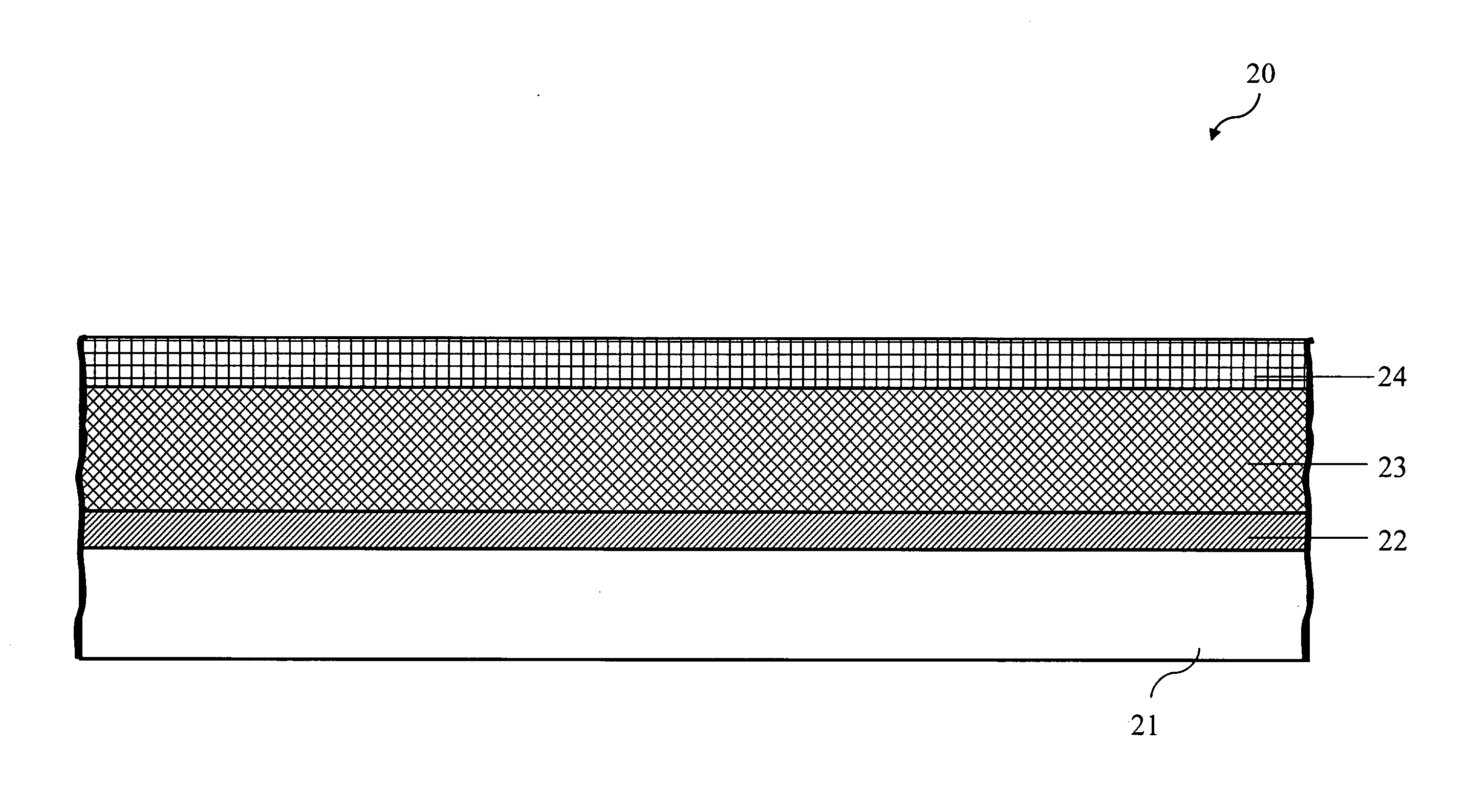
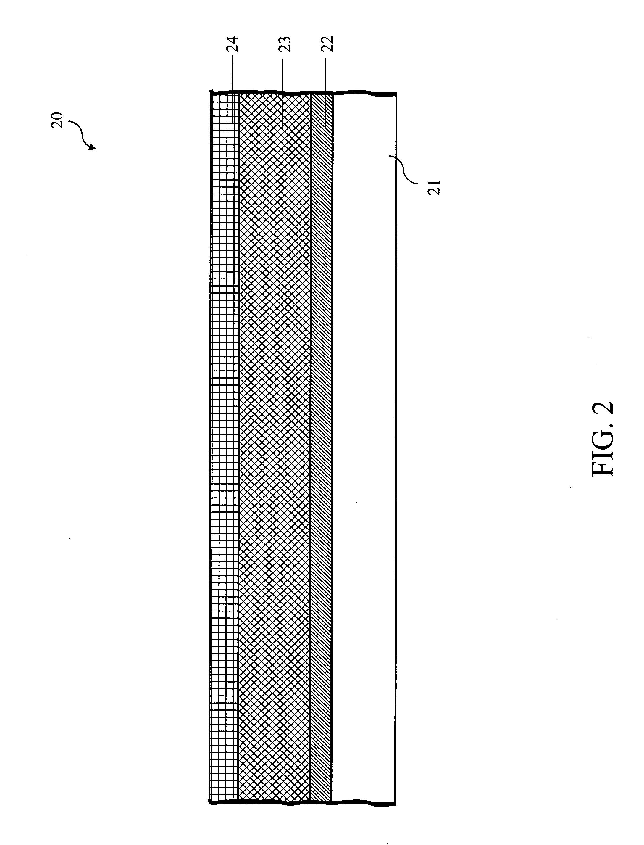
[0021]We first describe the structure of the disclosed thin film solar cell. FIG. 2 is a cross-sectional view of the first structure of thin film solar cell according to the invention. The thin film solar cell 20 includes: a substrate 21, a metal layer 22, an absorbing layer 23, and a passivation layer 24. The substrate 21 is made of a flexible material (also called soft material), glass, or polyimide (PI). In practice, the flexible material can be aluminum alloy foil, copper foil, and so on. Besides, the substrate 21 has to be first washed before subsequent sputtering and deposition.

[0022]The metal layer 22 forms on the substrate 21. In practice, the metal layer 22 is grown on the substrate 21 by sputtering Mo onto the substrate 21, and is used as a back electrode layer for conductin...


PUM

PropertyMeasurementUnit
thicknessaaaaaaaaaa
thicknessaaaaaaaaaa
structureaaaaaaaaaa

Abstract

A thin film solar cell structure and the fabricating method thereof are disclosed. A passivation layer is embedded into the thin film solar cell structure to be in contact with an absorbing layer. The interface trap density of the absorbing layer is reduced by the surface electric field of the passivation layer. The invention helps improve the power conversion efficiency and protect the absorbing layer.

Description

BACKGROUND OF THE INVENTION[0001]1. Field of Invention[0002]The invention relates to a solar cell structure and the fabricating method thereof. In particular, the invention relates to a thin-film solar cell structure that uses a chemical thin film as its absorbing layer and the fabricating method thereof.[0003]2. Related Art[0004]In recent years, the solar energy industry gradually turns its research emphasis from conventional wafer manufacturing to thin films. Compound thin films, in particular, receive particular attention. Compound thin film solar cells compared with wafer solar cells have many advantages, such as higher conversion efficiency, lower cost, wider absorbing range, more flexible, and possible for large area applications. Among various chemical compounds, copper indium gallium selenium (CIGS) materials have a wide absorbing spectrum. They can absorb more solar power to increase the conversion efficiency.[0005]Please refer to FIG. 1 for a cross-sectional view of the st...

Claims


Application Information

Patent Timeline
Patent Type & Authority Applications(United States)
IPC IPC(8): H01L31/0216H01L31/18C23C14/35
CPCH01L31/0322H01L31/0392Y02E10/541H01L31/1868H01L31/0749H01L31/03925H01L31/03928Y02P70/50
Inventor LIU, CHEE WEEHSU, WEN WEICHENG, TZU HUANHO, WEI SHUO
Owner NAT TAIWAN UNIV
Why Eureka
Try Eureka