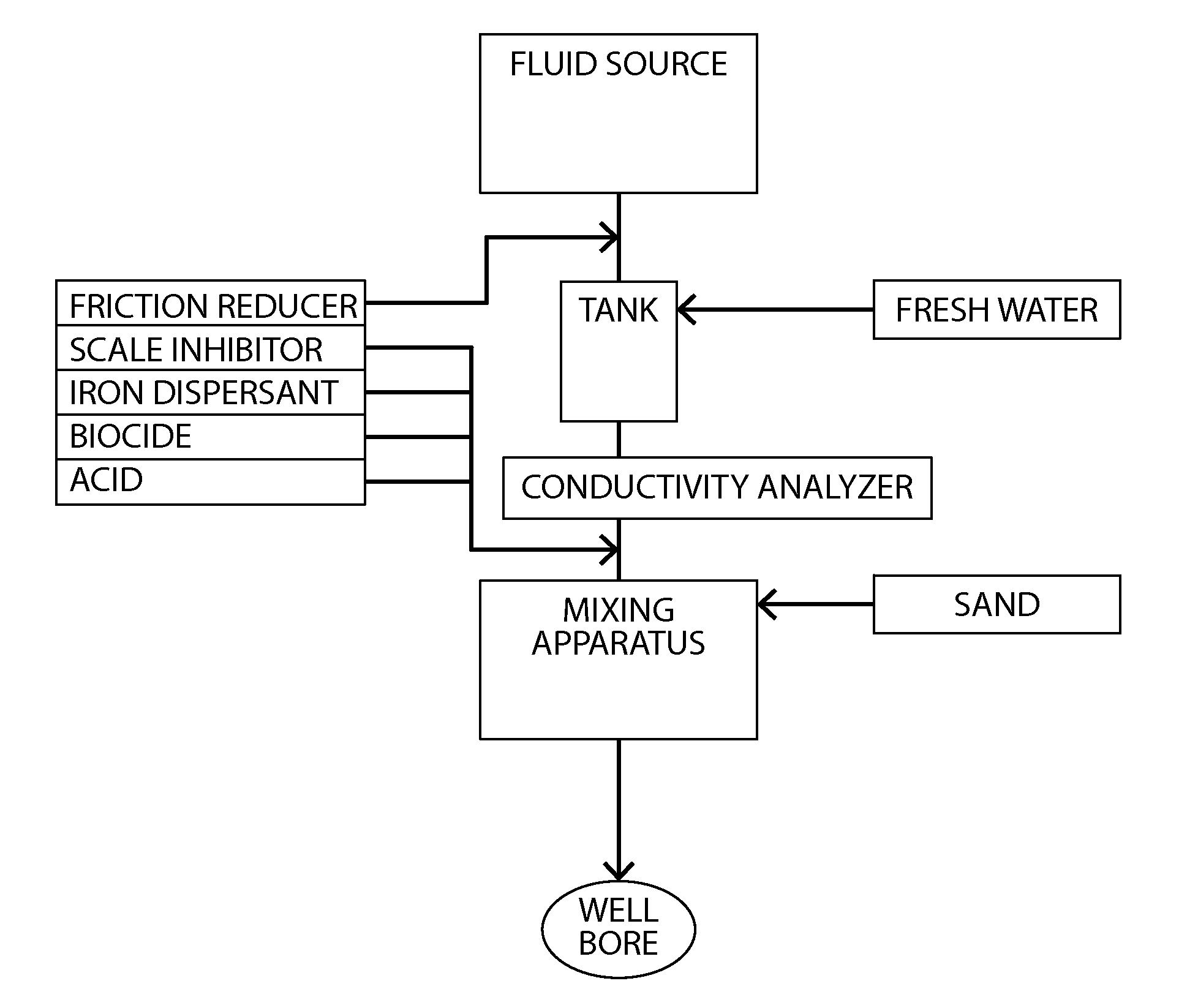
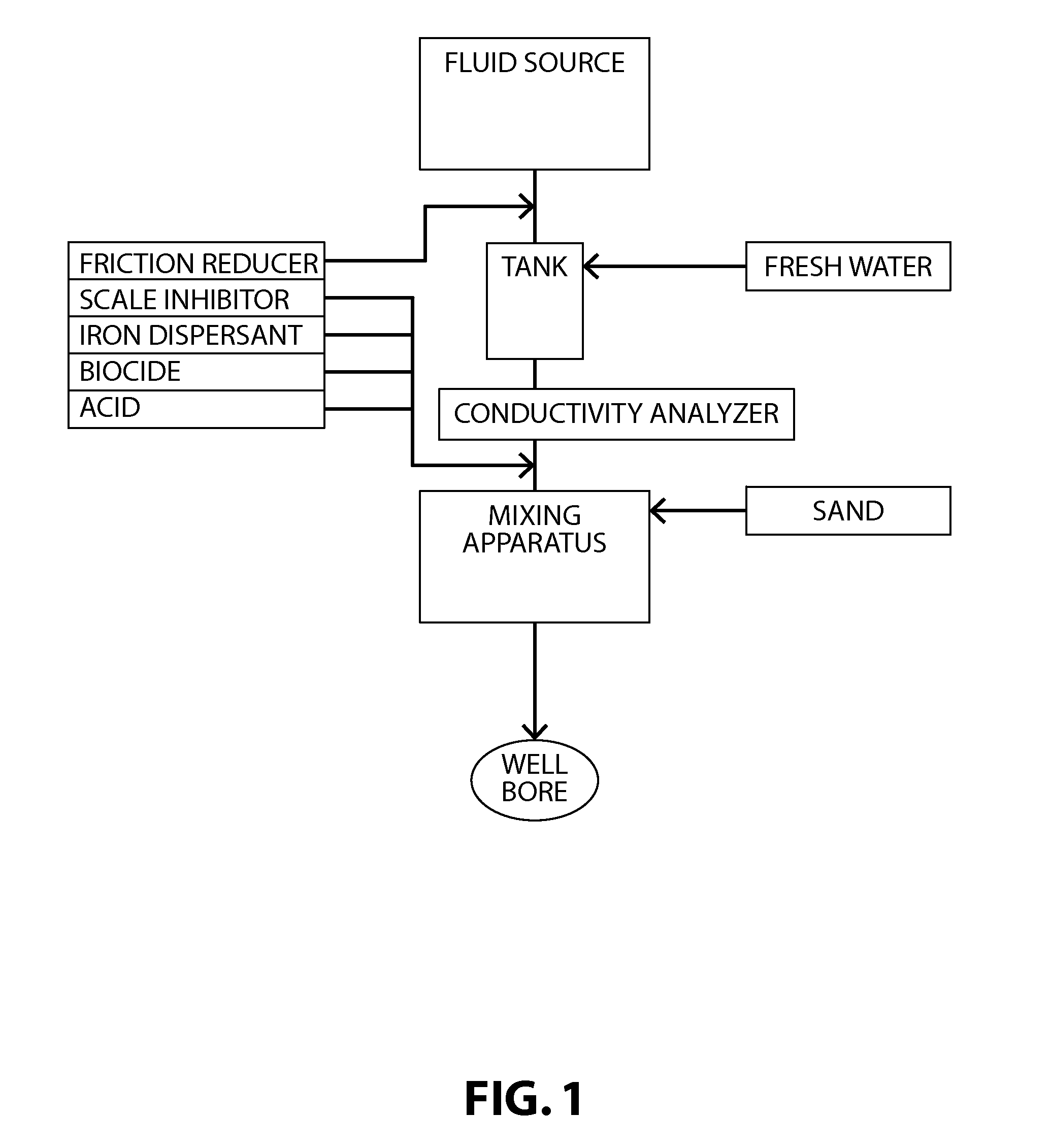
Fracturing fluid water reuse system and method

a fluid water reuse and fracturing technology, applied in the direction of sealing/packing, mixing, borehole/well accessories, etc., can solve the problems of cracks in formation, low porosity and permeability of rock, and extremely low natural permeability, so as to reduce the cost of fracturing fluid chemicals, the effect of reducing costs

Active Publication Date: 2012-02-02
CHEVROU USA INC
View PDF19 Cites 50 Cited by
  • Summary
  • Abstract
  • Description
  • Claims
  • Application Information

AI Technical Summary

Benefits of technology

[0026]Potential advantages of the invention include, but are not limited to, significantly reducing the costs associated with the reuse or disposal of produced fluid, reducing the costs of the fracturing fluid chemicals, reducing the costs associated with transporting fresh water to the well site, increasing well production by between 10 and 20%, and reducing the specific ion production in the produced water that causes increased treatment costs.

Problems solved by technology

Absent the formation of fractures in the rock formation, the porosity and permeability of the rock may be too low to allow for oil and gas to be recovered therefrom at an economic rate.
This is especially true of shale reservoirs, which typically have an extremely low natural permeability.
The increased pressure due to the high-pressure pumping of the fracturing fluid causes cracks to form in the formation.
The costs associated with transporting and storing water from other sources can greatly impact the economic viability of hydrofracturing-based oil and gas recovery.
Treatment and disposal of this produced fluid can add to the complexity and cost of the well's operation, typically requiring capturing and shipping the fluid to treatment facilities.
In some non-limiting embodiments of the inventive method, reaction of the Fenton's reagent can cause formation of complexes of iron and the suspended solids, which can cause coagulation and flocculation of the suspended solids.

Method used


Image

  • Fracturing fluid water reuse system and method
  • Fracturing fluid water reuse system and method

Examples


example

[0078]In this example, Table 3 illustrates two produced fluid samples from a Marcellus Shale well after addition of approximately 50% by volume production brine thereto. As can be seen, the conductivity of the samples is slightly above 150,000 μmhos / cm and the iron content is above 50 ppm. Each sample was observed to be black in color, presumably due to the presence of high amounts of suspended solids such as kerogen, residual polyacrylamide, and biofilm.

TABLE 3Produced Fluid Composition After Production Brine AdditionAnalysisPit #2Pit #3unitspH6.296.27Conductivity157,400162,700μmhos / cmSpecific Gravity1.1061.120Fluid Density9.229.34lb / galApprox. Salt Percentage19.617.2%Ca10,50511,432mg / LCa Hardness26,26328,580mg / LMg1,0341,122mg / LMg Hardness4,2394,600mg / LTotal Hardness30,50233,180mg / LTotal Iron52.261.7mg / LSulfates2013mg / LATPN / AN / ACarbonate Alkalinity0.00.0mg / LBicarbonate Alkalinity292.8292.8mg / LTotal292.8292.8mg / LBarium1,008.01,039.0mg / LStrontium3,380.03,616.0mg / L

[0079]The two sample...


PUM

PropertyMeasurementUnit
oxidation-reduction potentialaaaaaaaaaa
conductivityaaaaaaaaaa
oxidative strengthaaaaaaaaaa

Abstract

Methods of processing a fluid recovered from an oil or gas extraction operation for reuse in a hydraulic fracturing fluid are described. The methods include providing an amount of a produced fluid composition containing iron and suspended solids and controlling at least one of the conductivity, iron content, oxidative strength, and pH of the composition, such that Fenton's reagent is formed in situ. Also described are hydraulic fracturing fluids produced using fluid recovered from an oil or gas production process and treated in accordance with the methods described herein as well as systems for preparing a hydraulic fracturing fluid having, as a fluid source, fluid recovered from an oil or gas production process that has been treated in accordance with the methods described herein.

Description

CROSS REFERENCE TO RELATED APPLICATION[0001]This application claims priority to U.S. Provisional Patent Application No. 61 / 368,425, filed on Jul. 28, 2010, the entire contents of which are hereby incorporated by reference herein.BACKGROUND OF THE INVENTION[0002]1. Field of the Invention[0003]This application relates to methods and systems for treating fluids recovered from a subsurface oil or gas production process. More specifically, this application relates to methods and systems of treating flow back and / or production brine and preparing hydraulic fracturing fluids comprising the treated flow back and / or production brine.[0004]2. Description of Related Art[0005]Hydraulic fracturing, also referred to as “hydrofracking,” is a technique commonly used in the removal of oil and gas from subsurface rock formation reservoirs, and especially shale reservoirs. Hydraulic fracturing works by increasing the pressure in the formation rock so that fractures form. The fractures in the formation...

Claims


Application Information

Patent Timeline
Patent Type & Authority Applications(United States)
IPC IPC(8): E21B43/26B01F15/00B01F13/00E21B43/00C09K8/62
CPCC09K8/72C09K8/62
Inventor SVARCZKOPF, TIMOTHY C.WEAVER, III, DALTON R.BENDER, JON M.STRICKLER, JESSE J.
Owner CHEVROU USA INC
Why Eureka
Try Eureka