Optical coherence tomographic imaging apparatus

a tomographic imaging and optical coherence technology, applied in the field of tomographic imaging apparatus based on optical coherence tomography, can solve the problems of difficult control of delay line devices with high accuracy at high speed, conventional techniques described above, etc., and achieve the effect of improving depth resolution, low coherence light, and high depth resolution

Inactive Publication Date: 2012-02-02
CANON KK
View PDF5 Cites 13 Cited by
  • Summary
  • Abstract
  • Description
  • Claims
  • Application Information

AI Technical Summary

Benefits of technology

[0018]The OCT apparatus, which uses low coherence light, provides tomography with high depth resolution.
[0019]Also, the depth resolution is improving further due to increases in bandwidth of light sources. Under these circumstances, higher accuracy correction is required in order to prevent deformation in the depth direction.

Problems solved by technology

However, the conventional techniques described above have the following problems.
Consequently, a stage operating at high speed is loaded with multiple parts or a large part, making it difficult to control the delay line device with high accuracy at high speed.

Method used


Image

  • Optical coherence tomographic imaging apparatus
  • Optical coherence tomographic imaging apparatus
  • Optical coherence tomographic imaging apparatus

Examples


embodiments

First Embodiment

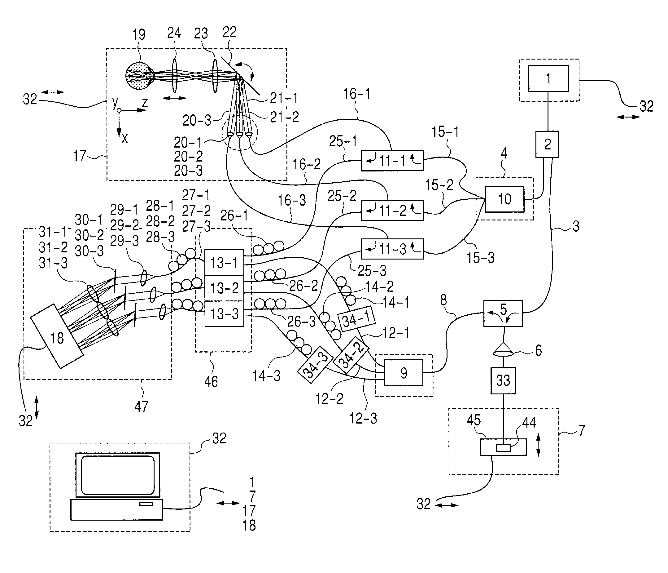
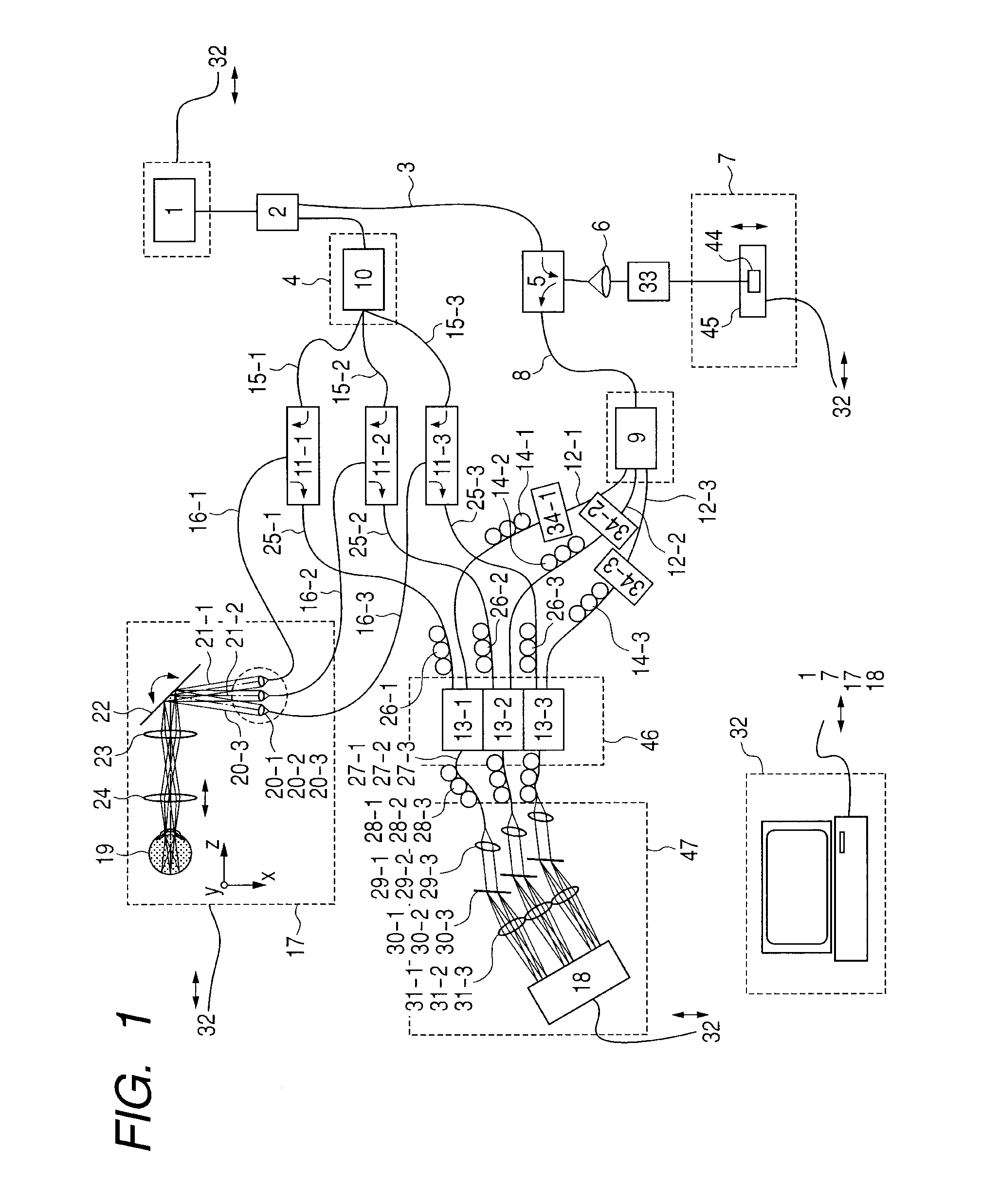
[0032]As a first embodiment, a configuration of an optical coherence tomographic imaging apparatus (OCT apparatus) resulting from application of the present invention will be described.

[0033]To put it briefly, first, light from an SLD light source is divided into a single reference light and single sample light by a fiber coupler, and optical path length of a reference-light path of the resulting reference light is changed.

[0034]After the change, the reference light is split into three lights by reference light splitting means. Also, the sample light is split into three lights—the same number of lights as the reference lights—by the sample light splitting means. Subsequently, each of the sample light is caused to pass through a circulator, led axially symmetrically with respect to the optic axis of an inspection object, i.e., an eye under examination, and directed at a surface to be irradiated, i.e., the retina in the back of the eye, through a collimator and multipl...

second embodiment

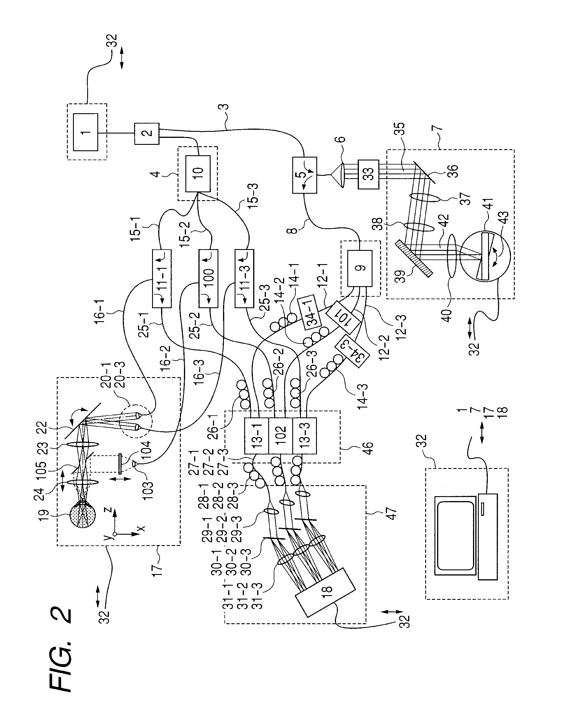
[0082]In a second embodiment, an exemplary configuration designed to provide high-resolution retinal tomographic images will be described, where the high-resolution retinal tomographic images are obtained through feedback control which involves feeding back detected movements of an eyeball in a z-axis direction to an OCT delay line.

[0083]According to the present embodiment, as with the first embodiment, out of multiple sample lights possessed by an optical coherence tomographic imaging apparatus, an arbitrary sample light is focused onto the cornea in the anterior segment of the eye and anteroposterior movement of the eyeball is measured.

[0084]By feeding back the measurement results to the delay line, high-quality retinal tomographic images can be obtained without being influenced by the movement of the eyeball.

[0085]FIG. 2 is a diagram illustrating principal parts of the optical coherence tomographic imaging apparatus (OCT apparatus) according to the present embodiment. FIG. 3 is a...


PUM


Abstract

Optical coherence tomographic imaging apparatus creating tomographic image of inspection object includes light splitting means for splitting light from light source into a single reference light and a single sample light, optical path length changing means for changing optical path length of the single reference light, reference light splitting means for splitting the single reference light whose optical path length is changed into a plurality of reference lights, sample light splitting means for splitting the single sample light into a plurality of sample lights, irradiation means for irradiating the inspection object by leading the plurality of sample lights thereto, interference signal forming means for combining returning lights of the plurality of the sample lights from the inspection object irradiated by the irradiation means with the plurality of reference lights passed through the reference-light path, and interference signal obtaining means for obtaining an interference signal from the interference signal forming means.

Description

TECHNICAL FIELD[0001]The present invention relates to an imaging apparatus based on optical coherence tomography, and more particularly, to an apparatus configuration capable of multi-beam interference processing and apparatus configuration for detecting anteroposterior motion of an eyeball and make corrections for the motion.BACKGROUND ART[0002]Recently, various optical instruments have come to be used to observe the ocular fundus as an inspection object. For example, an anterior segment imaging device, fundus camera, confocal scanning laser ophthalmoscope, and optical coherence tomographic imaging apparatus (low-coherence, optical coherence tomographic imaging apparatus: hereinafter referred to as an OCT apparatus) are used.[0003]Among others, the OCT apparatus, which allows tomographic images of the ocular fundus to be obtained at high resolution, is currently becoming an indispensable apparatus for specialized retinal outpatient clinics. Also, the OCT apparatus is finding applic...

Claims


Application Information

Patent Timeline
Patent Type & Authority Applications(United States)
IPC IPC(8): A61B3/14G01B9/02
CPCA61B3/102A61B5/0066A61B5/0073G01N21/4795G01B9/02044G01B9/02021G01B2290/35G01B9/02091G01B9/02068G01B2290/70G01B9/02077G01B9/02083G01B9/02027
Inventor MAKIHIRA, TOMOYUKIUTSUNOMIYA, NORIHIKO
Owner CANON KK
Why Eureka
Try Eureka