Industrial x-ray tube

a technology of industrial x-ray tubes and x-ray tubes, which is applied in the direction of x-ray tubes, x-ray tube cathode assemblies, x-ray tube details, etc., can solve the problems of increasing the probability of electrical current becoming unstable, large and heavy, and shortening the lifespan, so as to achieve optimal voltage

Inactive Publication Date: 2012-02-02
RIGAKU CORP
View PDF0 Cites 26 Cited by
  • Summary
  • Abstract
  • Description
  • Claims
  • Application Information

AI Technical Summary

Benefits of technology

[0048]The industrial X-ray tube according to the present invention may have voltage control means that controls a voltage applied between the cathode and the anode; wherein the voltage control part is capable of recording the voltage-current characteristics between the cathode and the anod

Problems solved by technology

X-ray tubes of such description present a problem in that they are large and heavy since a filament power supply is required in addition to a high voltage power supply.
A problem is presented in that portions that experience large localized currents degrade rapidly, increasing the likelihood of the electrical current becoming unstable, and shortening the lifespan.
Alth

Method used


Image

  • Industrial x-ray tube
  • Industrial x-ray tube
  • Industrial x-ray tube

Examples


first embodiment

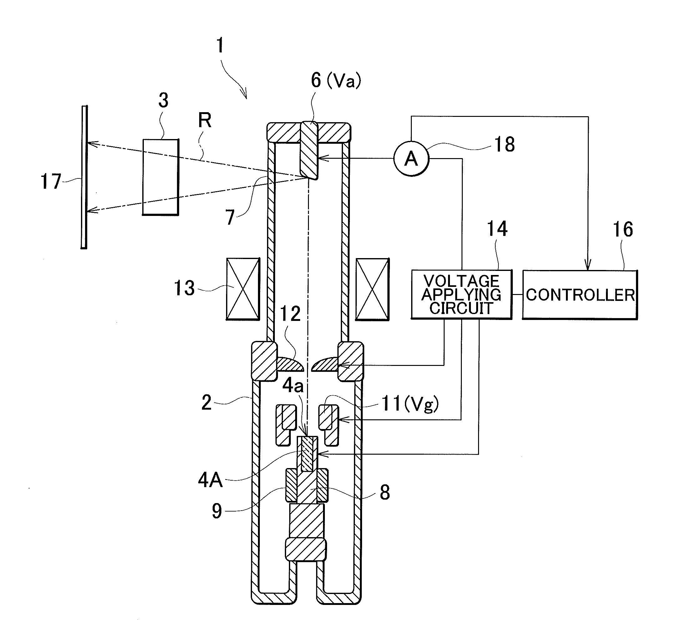
[0060]FIG. 1 shows a cross-sectional view of an embodiment of the industrial X-ray tube according to the present invention. The X-ray tube 1 according to the present embodiment has a sealing container 2 made from a ceramic (for example, alumina (Al2O3)) or glass. The sealing container 2 is shaped as a hollowed-out cylinder, and the interior thereof is maintained in a vacuum state. The sealing container 2 is electrically insulated by solid molding, immersion in an insulating oil, sealing-in of a high-pressure insulating gas, or a similar method; and then accommodated in a portable-type container. The sealing container 2 is carried by the measuring technician to a object 3 to be measured such as, for example, a frame of a construction structure.

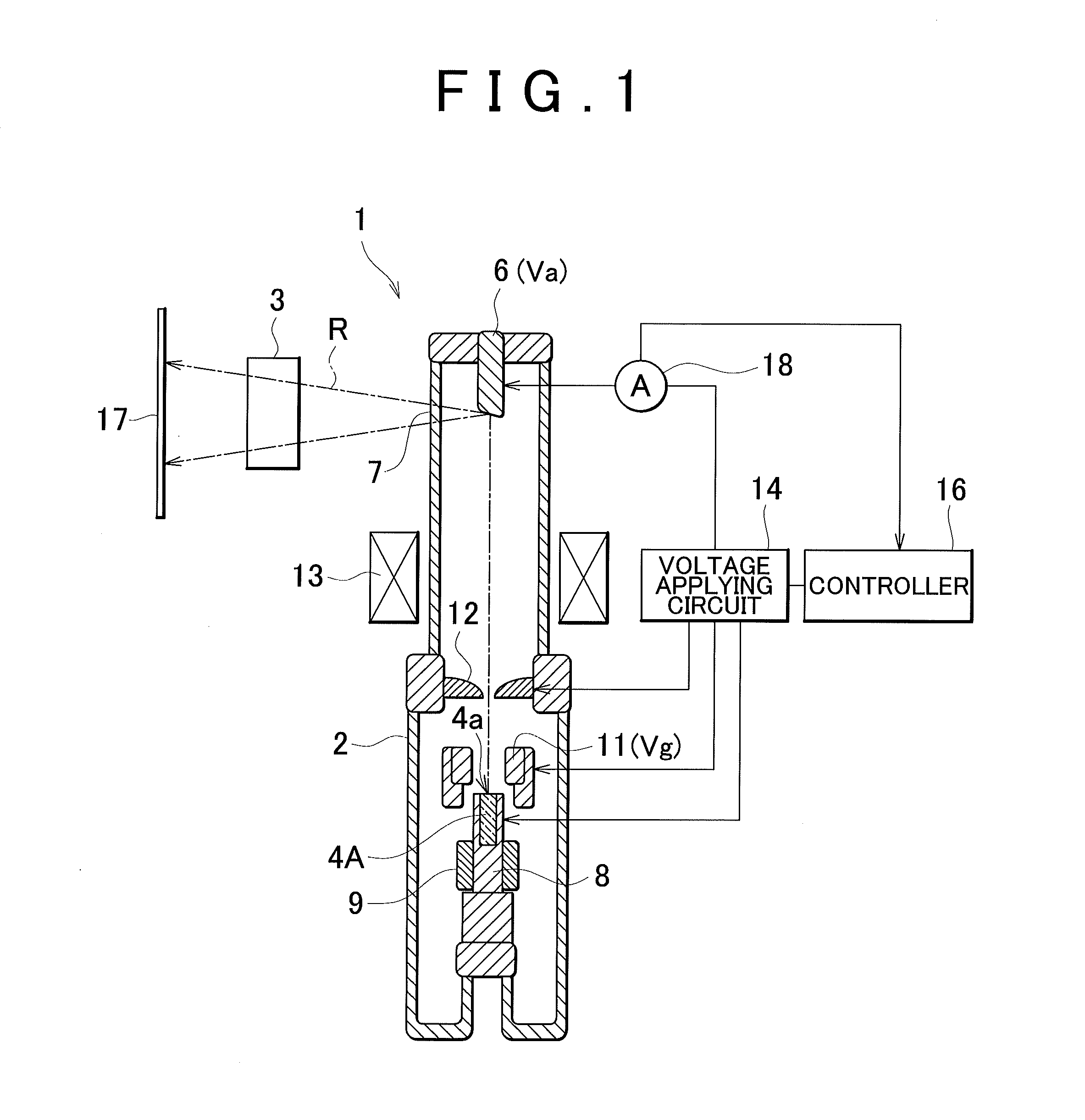
[0061]A cathode 4A is provided towards one end (the lower-end side in FIG. 1) of the interior of the sealing container 2, and an anode 6 is provided towards another end (the upper-end side in FIG. 1). It is known that structures exposed to a hi...

second embodiment

[0082]FIG. 7 is a cross-sectional view of another embodiment of the industrial X-ray tube according to the present invention. In FIG. 7, constituent elements that are identical to the constituent elements shown in FIG. 1 are affixed with identical numerals, and a description thereof shall not be provided.

[0083]In the X-ray tube 1 shown in FIG. 1, electrons released from the cathode 4A are caused to collide with the anode 6, and X-rays are emitted towards the sideway or the front of the anode 6. In contrast, in an X-ray tube 21 shown in FIG. 7, a transmission-type target is used as an anode 26. When electrons emitted by the cathode 4A collide with the anode 26, X-rays are emitted towards the rear of the anode 26.

[0084]An example of the transmission-type target is a sheet formed by layering tungsten (W) and beryllium (Be). If W is arranged on the inside of the X-ray tube, the accelerated electrons collide with the W sheet, and emit white X-rays and fluorescent X-rays which are transmi...

third embodiment

[0085]FIG. 9 shows another embodiment of the industrial X-ray tube according to the present invention. The X-ray tube according to this embodiment is the X-ray tube 1 shown in FIG. 1. It shall be apparent that the X-ray tube 1 may instead be the X-ray tube 21 shown in FIG. 7 or another X-ray tube having a similar structure.

[0086]The X-ray tube 1 is electrically insulated by solid molding, immersion in an insulating oil, sealing-in of a high-pressure insulating gas, or a similar method; and then accommodated in a portable-type container 25, along with a battery 24, a power supply circuit 30, and an electricity control system 27. The container 25 is secured on a wheeled platform 22. The wheeled platform 22 has wheels 23a, 23b. At least one of the wheels 23a, 23b is a driven wheel that is driven by a power source. A driving system including the power source is not shown. The wheels 23a, 23b may also be provided directly on the container 25, instead of the container 25 being placed on t...


PUM


Abstract

An industrial X-ray tube formed by accommodating a cathode and anode in a container having an evacuated interior, in which electrons emitted from the cathode are caused to strike the anode and X-rays are emitted from the anode. The cathode is formed from graphite. The graphite is a layered crystal obtained by layering a plurality of carbon hexagonal planes. The graphite is cut based on crystal axes of the carbon hexagonal planes. The resulting cut surface is caused to function as an electron-emitting surface. For example, directions of an a- and b-crystal axis may be set so as to be arbitrary between each of the layers of the carbon hexagonal planes, the graphite may be cut along a surface parallel to the c-axis, and the resulting cut surface may be caused to function as an electron-emitting surface. The graphite may also be cut along a surface orthogonal to the c-axis.

Description

BACKGROUND OF THE INVENTION[0001]1. Field of the Invention[0002]The present invention relates to industrial X-ray tubes that are used when performing non-destructive testing for plant piping and similar structures, where electrons emitted from the cathode are caused to strike the anode, and X-rays are radiated from the anode.[0003]2. Description of the Related Art[0004]Conventionally known industrial X-ray tubes of such description include those having a structure in which the cathode is formed from a filament, a current is applied whereby thermal electrons are emitted from the filament, and the thermal electrons are caused to strike the anode, whereby X-rays are emitted from the anode. X-ray tubes of such description present a problem in that they are large and heavy since a filament power supply is required in addition to a high voltage power supply.[0005]Although outside the field of X-ray tubes, electron-emitting elements in which carbon nanotubes emit electrons based on field e...

Claims


Application Information

Patent Timeline
IPC IPC(8): H05G1/32H01J35/06
CPCH01J35/065H01J2235/16H01J2235/062H01J35/16
Inventor OGATA, KIYOSHITAKEDA, YOSHIHIROKANI, TETSUOKANBE, MAKOTOOSAKA, NAOHISASATO, TAKAHISA
Owner RIGAKU CORP
Why Eureka
Try Eureka