Ash And Solids Cooling In High Temperature And High Pressure Environment

a technology of high temperature and high pressure environment, applied in the field of cooling of solid particles, can solve the problems of local damage to the refractory, and overheating of the vessel wall

Active Publication Date: 2012-02-09
THE SOUTHERN CO
View PDF8 Cites 15 Cited by
  • Summary
  • Abstract
  • Description
  • Claims
  • Application Information

AI Technical Summary

Benefits of technology

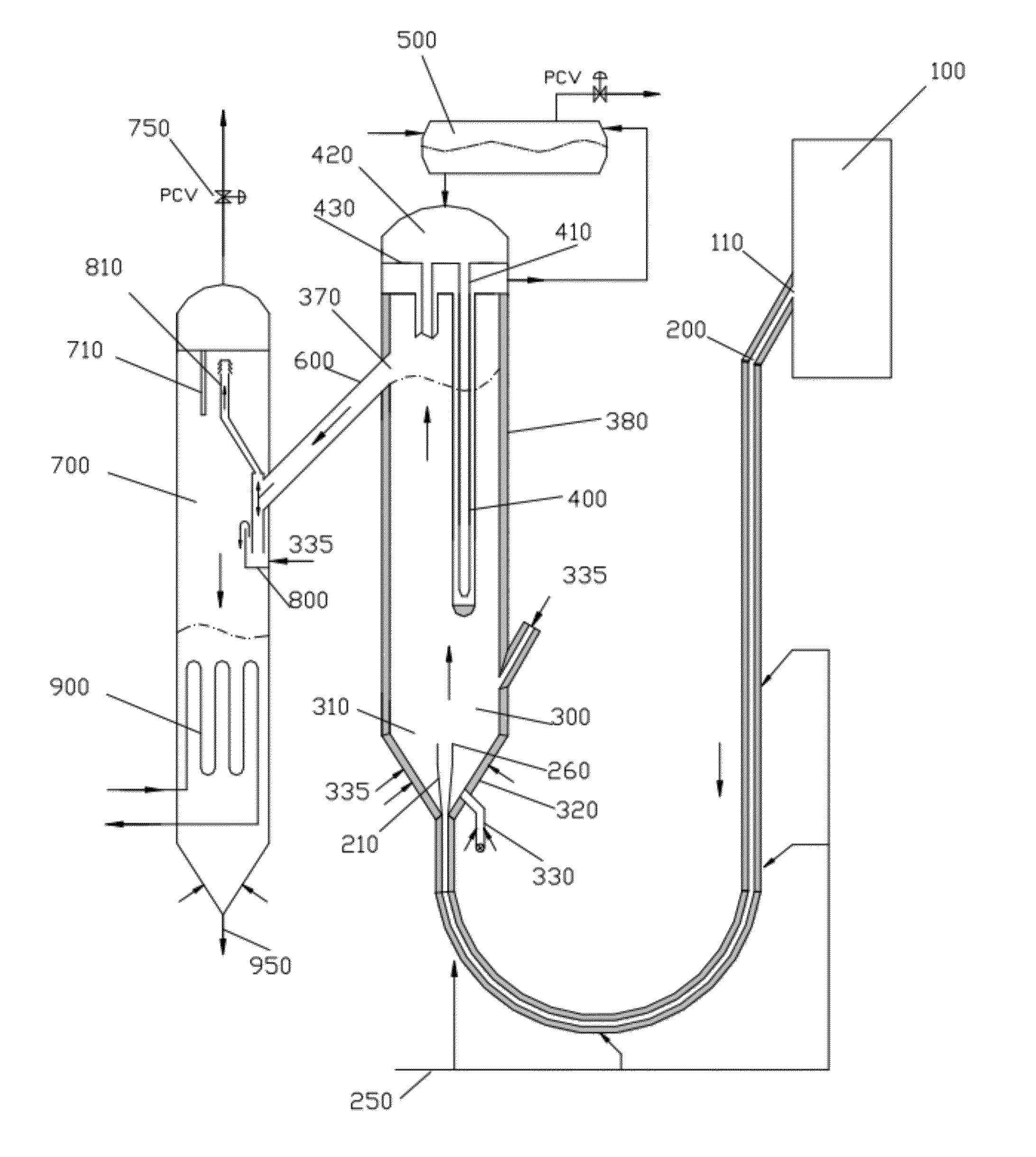
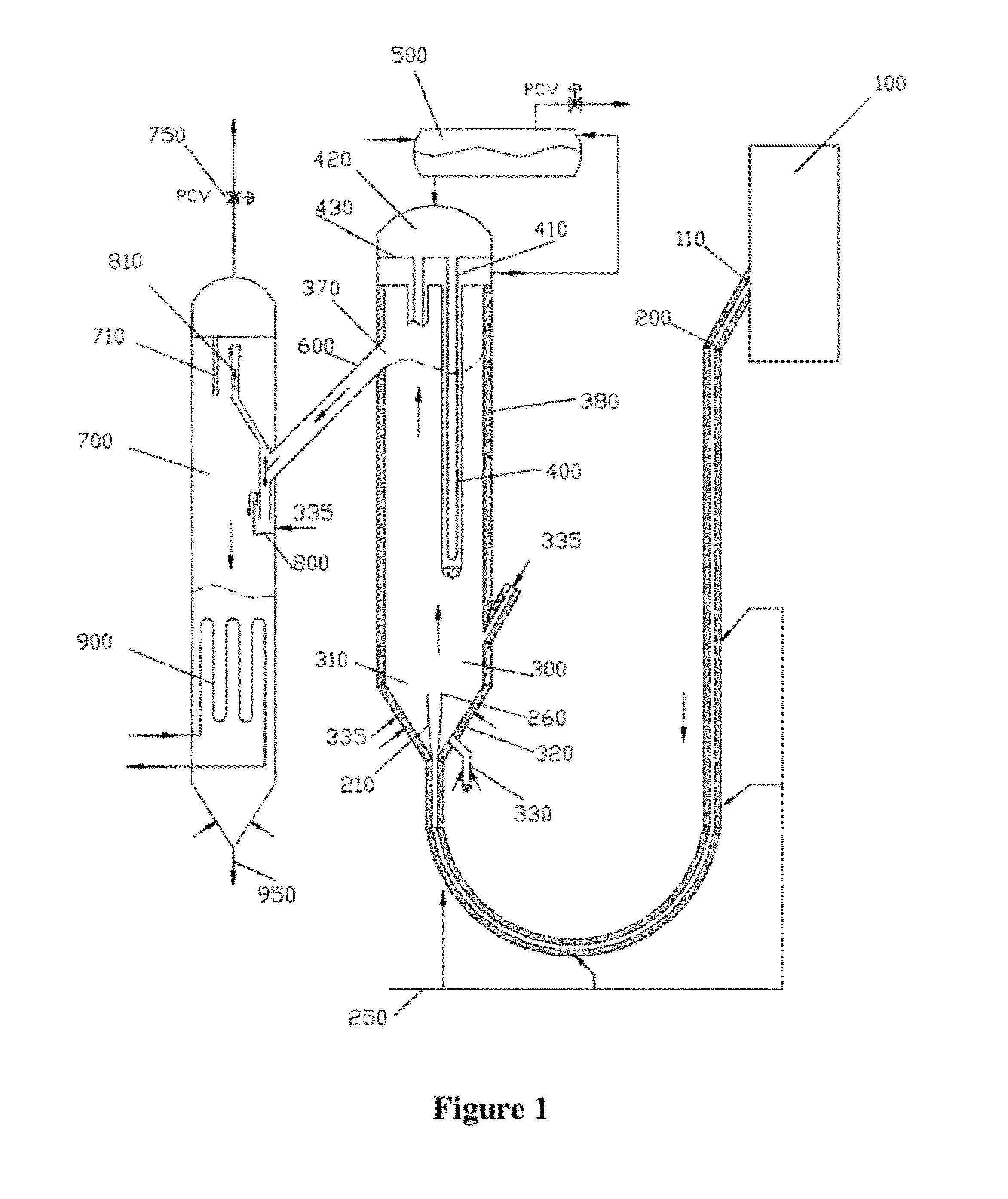
[0043]Aeration can be added to the connecting downcomer pipe to control the solids flow due to hydrostatic head created by elevation differences. The aeration rate can be adjusted to have all the aeration gas flow downward along with the solids avoiding disturbance to gasifier or reactor operation. The solids flow control can also be adjusted by balancing the pressure difference between the gasifier and the cooler vessel with a vent pressure control valve.
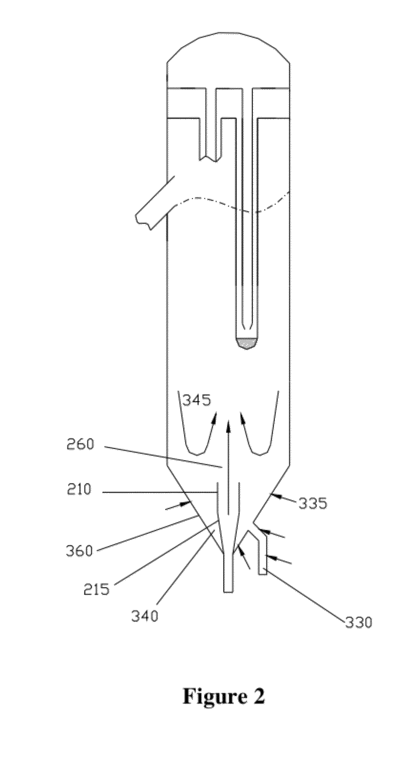
[0044]Extraneous materials from the gasifier can be separated from hot solid particles with sufficient aeration in the bottom cone portion of the primary solids cooler.

Problems solved by technology

A first challenge is supporting the heat exchanger tubes that will exchange the heat from the solids to a cooling media.
The difficulty in this issue is that the support has to be anchored to the outside wall, penetrating through layers of refractories that are necessary to resist the erosion due to movement of solid particles (in the mass mean diameter size range of from approximately 50 microns to 400 microns), and to insulate the wall from overheating.
The vibration of the support can damage the refractory, and cause the vessel wall to locally overheat.
Heat conduction through the support can also overheat the vessel walls, damaging and deforming the vessel.
This is a serious concern as the vessel forms the pressure boundary.
A second challenge in the development of a high pressure, high temperature heat exchanger is to achieve appropriate control of the solids flow to the heat exchanger without interfering with the operation of the gasifier or reactor from which the solids are being withdrawn and / or to which the cooled solids are being returned.
Also, for the circulating fluidized bed gasifier, when the solids are withdrawn from the standpipe, the aeration gas cannot be returned to the standpipe or the gasifier due to pressure restrictions.
Handling of the vent gas is difficult as the gas entrains fines at high process temperatures.
Under these circumstances, a challenge becomes how to vent the aeration gas and a portion of the gas entrained by the solids.
A fourth challenge in cooler equipment design involves appropriate handling of foreign and extraneous materials that originate from or pass through the gasifier.
Foreign and extraneous materials in the process result from, for example, contaminated feed, chipped refractory, broken gasifier internals and clinkers and slag formed during the process due to variability in feed fuel (coal, for example) or improper operation.
These materials are generally oversized and need to be removed from the process before reaching the heat exchanger surfaces to limit or prevent blockages in the flow path of hot solids.
As one of skill in the art appreciates, however, with gasifier operation, it is highly desirable to discharge extraneous materials from the gasifier, as accumulation of extraneous materials in the gasifier can cause various operating issues including formation of clinkers in the gasifier.
It is difficult to return such a large amount of gas flow through the cooler to the gasifier or combustor without interfering with its normal operation.
Another issue with the FCC references is that if the extraneous materials, which are common in gasification and combustion processes, pass through the cooling bundle, they can segregate and accumulate in the bottom of the cooler, eventually interfering with the normal operation of the cooler, since the FCC design has the solids downward flow and side withdrawal near the bottom.
It is difficult to apply these teachings to cool the gasifier solids with a broad particle size distribution such as from a fluidized bed or a circulating fluidized bed gasifier.
As one of skill in the art appreciates, however, with gasifier operation, the operating temperature can reach as high as approximately 2000° F.; thus, the materials selection can be a challenge or the materials cost will be prohibitive when the hot solids at such high temperatures directly contact the heat transfer surface.
However, in Kokko's design, solids have to make turns in three chambers that naturally makes the flow of solids more complex and more difficult to handle extraneous materials.
However, the large particle ash chamber does not have a cooling surface, and therefore the ash withdrawn from the chamber is essentially the same temperature as that in the combustor.
It is also difficult to achieve good separation of coarser and finer particles in a fluidized bed.
In Maryamchik et al., the fluidization gas returns back to the combustor, a practice which may not be feasible for some applications.
As one of skill in the art appreciates, however, with gasifier operation at high pressure, the cooling surface penetrating the wall can become a serious safety issue, and no known solution exists, other than to avoid it altogether.
Further, the cooling surface in the heat exchanger will still be in contact with finer particles essentially at the same high temperature of approximately 1600° F. as that in the combustor, necessitating the use of expensive engineering alloy materials for heat transfer surfaces.
This combination of large purge gas flows and handling the high temperature particles increases the material, fabrication and operation costs.
In Liu, all the purge and fluidization gas flows back to the gasifier, impeding operations if the flow is excessive.
Further, the cooling surface of Liu penetrates the refractory and vessel walls of the cooler causing potential difficulties with cooler wall design even with gasifier operating pressures being less than approximately 50 psi.
During operation, the cooling surface contacts solid particles that are near the high gasifier operating temperatures, which leads to challenging and expensive design.

Method used


Image

  • Ash And Solids Cooling In High Temperature And High Pressure Environment
  • Ash And Solids Cooling In High Temperature And High Pressure Environment
  • Ash And Solids Cooling In High Temperature And High Pressure Environment

Examples


Embodiment Construction

[0072]To facilitate an understanding of the principles and features of the various embodiments of the invention, various illustrative embodiments are explained below. Although exemplary embodiments of the invention are explained in detail, it is to be understood that other embodiments are contemplated. Accordingly, it is not intended that the invention is limited in its scope to the details of construction and arrangement of components set forth in the following description or illustrated in the drawings. The invention is capable of other embodiments and of being practiced or carried out in various ways. Also, in describing the exemplary embodiments, specific terminology will be resorted to for the sake of clarity.

[0073]It must also be noted that, as used in the specification and the appended claims, the singular forms “a,”“an” and “the” include plural references unless the context clearly dictates otherwise. For example, reference to a component is intended also to include composit...


PUM


Abstract

Disclosed are cooling and depressurization system equipment, arrangement and methods to cool solid particles from a coal gasifier operating at high temperature and pressure. Ash from the coal needs to be continuously withdrawn from a circulating fluidized bed gasifier to maintain the solids inventory in the gasifier. The system disclosed enables use of conventional materials of construction for heat transfer surfaces. The supports for the cooling surfaces are located on the lower temperature upper section of the primary cooler. The cooled solids along with the fluidizing gas exits the primary cooler to a secondary receiving vessel where the solids can be further cooled by conventional means. The fluidizing and entrained gas entering the secondary vessel is filtered and vented through a vent pressure control valve. The column of cooled solids in the secondary vessel is depressurized by a continuous depressurization system to low pressures which are sufficient for conveying the solids to silos for disposal. The system and methods proposed are equally applicable to many high temperature, high pressure processes that require cooling and depressurization of process solids.

Description

CROSS-REFERENCE TO RELATED APPLICATIONS[0001]This application claims the benefit of U.S. Provisional Application No. 61 / 372,008 filed 9 Aug. 2011, the entire contents and substance of which are hereby incorporated by reference.BACKGROUND OF THE INVENTION[0002]1. Field of the Invention[0003]The invention relates generally to the cooling of solid particles from applications that are operating at relatively high temperatures and pressures. It is particularly related to cooling high temperature ash from a coal gasifier operating in a temperature range of from approximately 1500° F. to 2200° F., and a pressure range of from approximately 30 to 1000 psia.[0004]2. Description of Related Art[0005]The cooling of hot solids from a gasifier or reactor that is operating in the temperature range of from approximately 1500° F. to 2200° F., and a pressure range of from approximately 30 to 1000 psia presents numerous challenges, none of which have all be overcome by conventional systems.[0006]A fir...

Claims


Application Information

Patent Timeline
Patent Type & Authority Applications(United States)
IPC IPC(8): F28F9/00F28F19/00
CPCF23C10/24F28D2021/0045F23J1/02F23J2900/01002F28D21/001C10J2300/1625C10J2300/1861C10J2300/1892C10J3/523C10J3/76C10K1/024C10J2300/093C10K1/022F28D7/12F28D13/00F23C2900/10006Y02E20/18
Inventor VIMALCHAND, PANNALALLIU, GUOHAIPENG, WANWANG
Owner THE SOUTHERN CO
Why Eureka
Try Eureka