Air separation method and apparatus

a technology of air separation and air stream, which is applied in the direction of lighting and heating equipment, solidification, refrigeration and liquid storage, etc. it can solve the problems of increasing the energy cost of inline barrel compressors, and reducing the pressure of boosted air streams. , to achieve the effect of lessening the pressure, reducing the pressure of boosted air streams, and reducing the flow rate of such streams

Inactive Publication Date: 2012-02-16
PRAXAIR TECH INC
View PDF5 Cites 13 Cited by
  • Summary
  • Abstract
  • Description
  • Claims
  • Application Information

AI Technical Summary

Benefits of technology

[0014]The effect of simultaneously vaporizing a liquid nitrogen stream in the higher pressure heat exchanger, in addition to heating the pumped liquid oxygen stream is to alter the shape of the composite cooling curve such that it enables the designer to lessen the pressure that would otherwise be required of the boosted pressure air stream to heat an oxygen stream at a supercritical pressure to a supercritical temperature if such oxygen stream were the only stream being heated within the higher pressure heat exchanger. In this regard, in a non-banked heat exchanger arrangement, all of the streams to be warmed and cooled are passed in indirect heat exchange within a single heat exchanger that in most practical applications is a series of heat exchangers run in parallel. Where the designer desires to decrease the pressure of the boosted pressure air stream, a problem that arises is that the flow rate of such stream must be increased. Where the liquid nitrogen stream is vaporized, the change in shape of such curves allows the flow rate of the boosted pressure air stream to be lower than that had such liquid nitrogen stream not been present. The higher flow rate results in more liquid air being produced that will result in a loss of column performance and at an extreme, will not allow column operation. In the banked case in which all of such heat exchange takes place within a higher pressure heat exchanger, the liquid nitrogen vaporization allows such heat exchanger to function at a reasonable approach temperature at the point within the heat exchanger at which the liquid oxygen becomes a supercritical fluid, typically 5 degrees Kelvin or less. If the liquid nitrogen were not present, not only would the heat exchanger not function at the flow rate required with the liquid nitrogen, but at an extreme of operation, the heating and cooling curves would in fact cross preventing any operation of the heat exchanger.

Problems solved by technology

The use of such heat exchanger banking saves fabrication costs in that it is only the higher pressure heat exchanger that must be fabricated to withstand the high oxygen pressure and the even higher pressures of the boosted air stream that are necessary to heat the oxygen.
The problem with this is that the cost in fabricating such a heat exchanger to withstand the pressure of the boosted air stream can become prohibitively expensive, as well as the cost of the associated pipework and valves which must also be rated to the same very high pressure.
In addition, there can be increased energy costs in that an inline barrel compressor might be required, depending on the pressure, that has an efficiency that is less than an integrally geared compressor that could be employed at a lower pressure.
Finally, during the startup of such a system the consequences of a failed pressure test at very high pressures can be quite severe.

Method used


Image

  • Air separation method and apparatus
  • Air separation method and apparatus
  • Air separation method and apparatus

Examples


Embodiment Construction

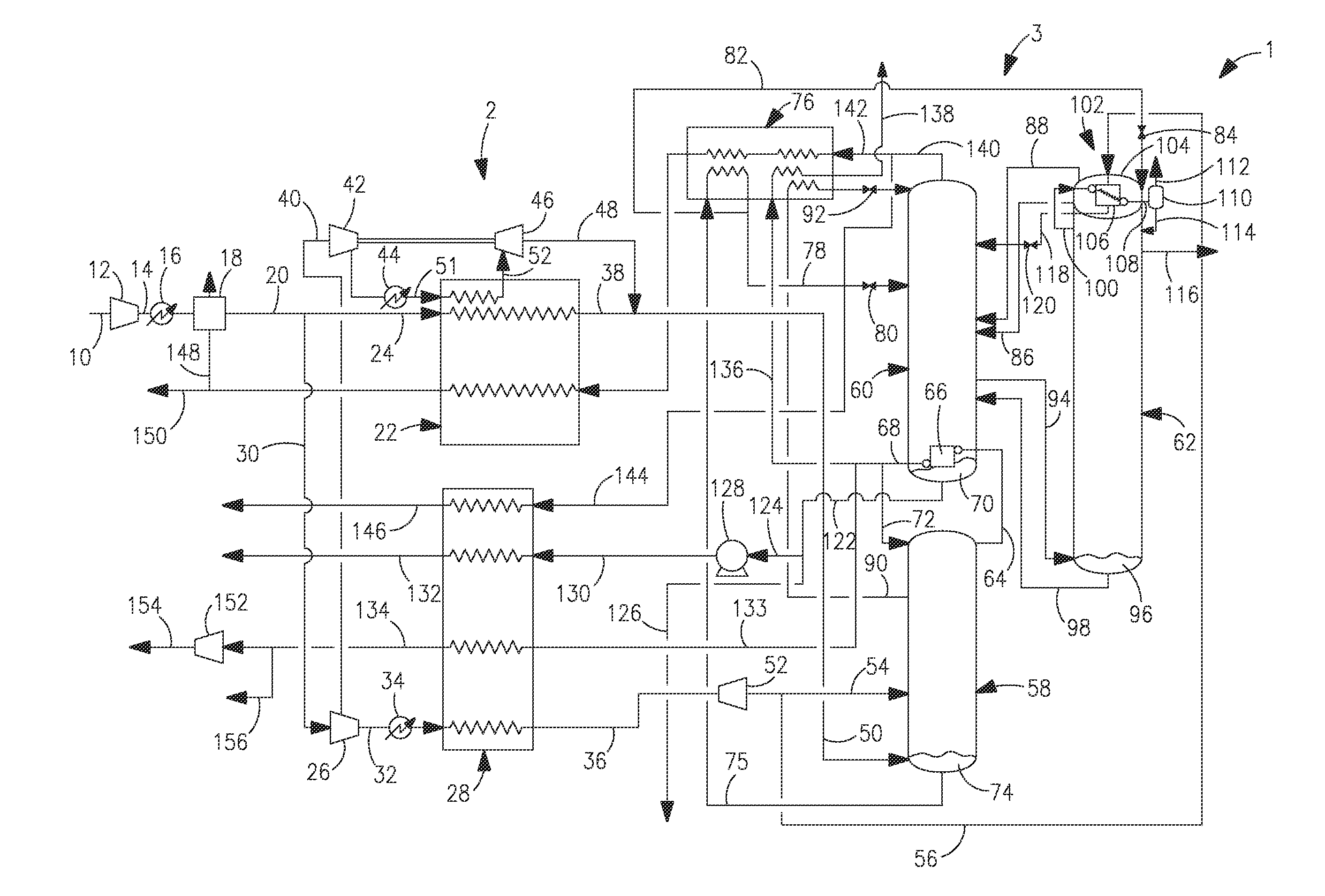
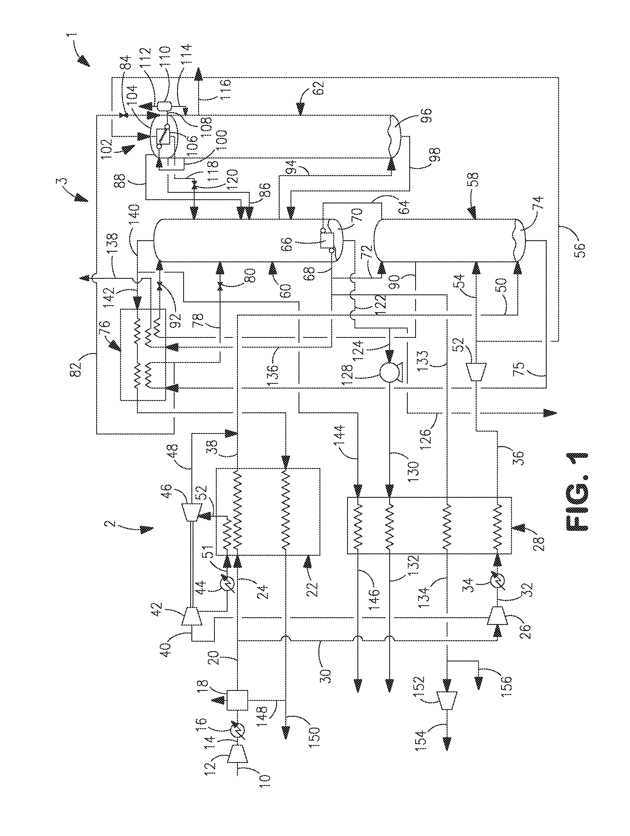
[0033]With reference to FIG. 1, a cryogenic rectification plant 1 is illustrated that is designed to separate compressed and purified air and thereby to produce an oxygen product as a supercritical fluid. Cryogenic rectification plant 1 is provided with a banked heat exchanger arrangement 2 and an air separation unit 3. Air separation unit 3 preferably, for reasons that will be discussed, is provided with an argon column 62 to produce an argon product. The banked heat exchanger arrangement 2 has a lower pressure heat exchanger 22 that operates at a lower average pressure than a higher pressure heat exchanger 28 thereof. The oxygen product is discharged from the higher pressure heat exchanger 28 as an oxygen product stream 132. Additionally, a nitrogen product stream 134 is also discharged from the higher pressure heat exchanger 28. It is understood, however, that the present invention has equal application to a cryogenic rectification plant that employs only a non-banked heat exchan...


PUM


Abstract

An air separation method and apparatus in which a supercritical oxygen product is produced by heating a pumped liquid oxygen stream having a supercritical pressure, through indirect heat exchange with a boosted pressure air stream. The indirect heat exchange is conducted within a heat exchanger and a liquid nitrogen stream is vaporized in the heat exchanger to depress the pressure that would otherwise be required of the boosted pressure air stream to heat the pumped liquid oxygen stream. The pumped liquid oxygen stream constitutes 90 percent of the oxygen-rich liquid removed from an air separation unit in which the air is rectified, the liquid nitrogen constitutes at least 90 percent of the liquid nitrogen that is not used as reflux and a flow-rate ratio between the liquid nitrogen stream and the oxygen-rich liquid is between about 0.3 and 0.90.

Description

RELATED APPLICATION[0001]This application claims the benefit of U.S. patent application Ser. No. 12 / 855,313, filed on Aug. 12, 2010, which is incorporated herein by reference.FIELD OF THE INVENTION[0002]The present invention relates to a method and apparatus for separating air in which oxygen-rich liquid is pumped to produce a pumped liquid oxygen stream having a supercritical pressure that is in turn warmed to a supercritical temperature through indirect heat exchange with a boosted pressure air stream to produce an oxygen product as a supercritical fluid. More particularly, the present invention relates to such a method and apparatus in which a liquid nitrogen stream is simultaneously vaporized while the pressurized liquid stream is heated, so as to depress the pressure that would otherwise be required of the boosted pressure air stream to heat the pumped liquid oxygen stream alone.BACKGROUND OF THE INVENTION[0003]There exists an emerging market for very high pressure supercritica...

Claims


Application Information

Patent Timeline
Patent Type & Authority Applications(United States)
IPC IPC(8): F25J3/04
CPCF25J3/04084F25J3/0409F25J3/04218F25J3/04296F25J3/04387F25J3/04412F25J3/04678F25J2240/10F25J2290/12F25J3/04957F25J2230/24F25J2230/40F25J3/0423
Inventor PROSSER, NEIL MARKJIBB, RICHARD JOHNSALGE, JAMES RICHARDZAMBRANO, LYDAWARTA, ANDREW M.
Owner PRAXAIR TECH INC
Why Eureka
Try Eureka