
Xenon flash lamp

a technology of flash lamps and xenon, which is applied in the direction of electric discharge lamps, basic electric elements, electrical appliances, etc., can solve the problems of large variations in the intensity of light entering the instrument, the position of the arc discharge tends to move, and the image of the arc does not consistently fall uniformly, so as to improve the stability of the arc struck, increase the proportion of light, and the effect of increasing the efficiency of light collection

Inactive Publication Date: 2012-02-16
AGILENT TECH AUSTRALIA M
View PDF7 Cites 0 Cited by
  • Summary
  • Abstract
  • Description
  • Claims
  • Application Information

AI Technical Summary

Benefits of technology

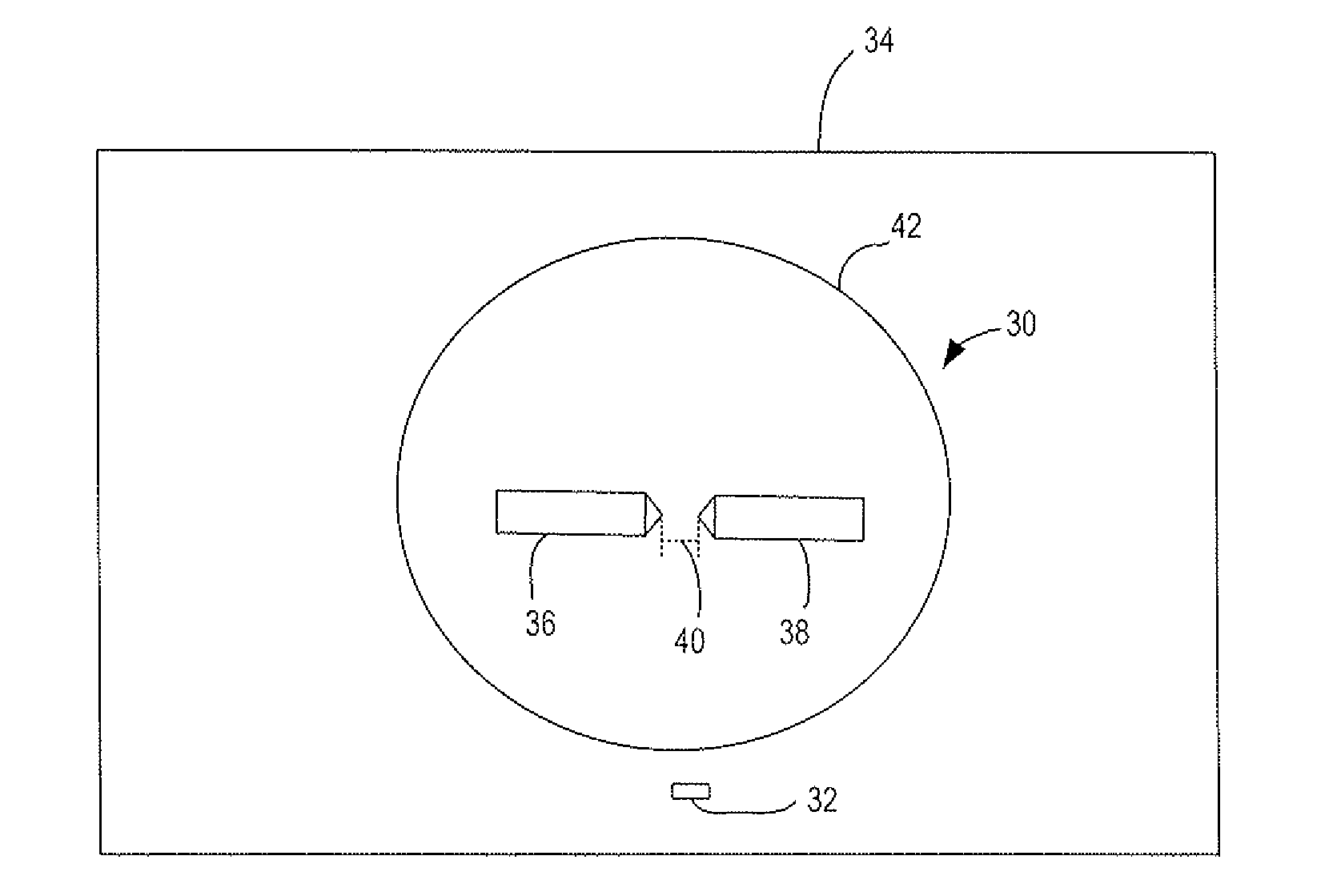
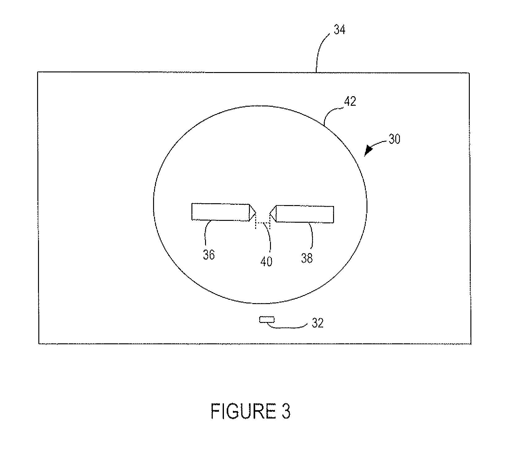
[0011]The effect of the invention is to improve stability of the arc struck between the anode and cathode and thereby to increase the proportion of light from the arc falling over the entrance aperture of the spectroscopy instrument. This allows imaging of a larger fraction of the total arc length leading to greater light collection efficiency. The combination of reduced movement of the arc and increased light collection efficiency may produce a useful reduction of noise in the output of the spectroscopy instrument.
[0012]The distance between the anode and the cathode may be such that in use, an arc struck between them has an aspect ratio (arc length to arc diameter) that substantially matches the aspect ratio of the entrance aperture (aperture length to aperture width) of the spectroscopy instrument.
[0013]Modern spectroscopy instruments are required to work with smaller and smaller sample volumes, which dictate entrance apertures with low aspect ratios of around 3:1 or 4:1. The spacing of the anode and the cathode of the lamp of the pulsable light source of the present invention may be, for example, less than 1.5 mm, providing an arc aspect ratio of 6:1 or less. Having a smaller aspect ratio has the benefit that a larger fraction of the total light produced by the lamp may be used, yielding potentially greater light throughput.
[0014]The shorter arc length also reduces the amount of random arc wander over the discharge path, increasing the stability of the arc. This means that more of the arc may be imaged onto the entrance aperture.
[0015]Having a shorter arc length, however, may put too large a fraction of the supply voltage drop into the electrode / gas interface region and not enough into the arc itself, reducing the efficiency of conversion of electricity into light. This may be addressed by increasing the xenon gas pressure inside the sealed envelope, for example, to greater than 1 atmosphere.
[0016]In an embodiment, the spacing of the anode and the cathode is between 0.5 mm and 1 mm and the pressure of xenon gas within the sealed envelope is between 2 and 4 atmospheres.

Problems solved by technology

A problem with xenon flash lamps is that the position of the arc discharge tends to move from one flash to the next.
A consequence of the change in the position of the arc is that the image of the arc does not consistently fall uniformly over the entrance slit.
This causes large variations in the intensity of light entering the instrument from one flash to the next.
These variations in light intensity are manifested as noise in the output of the instrument.
This represents a serious limitation on the performance achievable from a spectroscopy instrument using a xenon flash light source.
Even when all recommendations are followed, the noise performance of a spectroscopy instrument equipped with known xenon flash lamps is insufficient to meet many spectroscopic requirements.

Method used


Image

  • Xenon flash lamp
  • Xenon flash lamp
  • Xenon flash lamp

Examples


Embodiment Construction

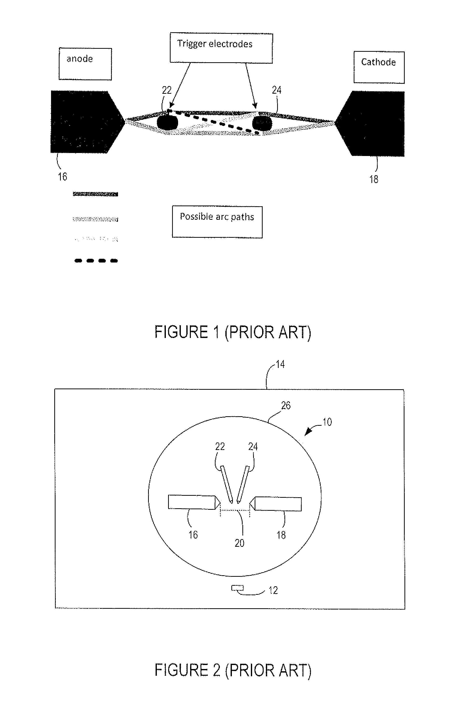
[0030]FIGS. 1 and 2 schematically illustrate a prior art xenon flash lamp 10. FIG. 2 also illustrates an entrance aperture 12 of a spectroscopy instrument 14. Spectroscopy instruments are known and so further details of the instrument have not been shown.

[0031]The xenon flash lamp 10 includes an anode 16 and a cathode 18 spaced apart by a distance 20 (shown in FIG. 2) and arranged so that their tips face each other. The distance 20 between the anode 16 and cathode 18 may be 1.5 mm, 3 mm or 8 mm. One or more trigger electrodes 22 and 24 are located between the anode 16 and cathode 18. The anode 16 and cathode 18 and trigger electrodes 22 and 24 are sealed within an envelope 26 of xenon gas pressurized to about 1 atmosphere.

[0032]In operation, the cathode 18 is connected to ground and an anode capacitor (not shown) is connected between the anode 16 and cathode 18. The anode capacitor is charged to a voltage, for example between about 200 and 1000 volts. This voltage is insufficient to...


PUM


Abstract

A pulsable light source for a spectroscopy instrument is provided, the light source including a xenon flash lamp having an anode and a cathode within a sealed envelope of pressurized xenon gas, the anode and the cathode being spaced so that an arc can be struck between the anode and the cathode without the use of a trigger electrode.

Description

CROSS REFERENCES TO RELATED APPLICATIONS[0001]This application claims the benefit of Australian Patent Application No. 2010903680 filed on Aug. 16, 2010, the subject matter of which is hereby incorporated by reference.TECHNICAL FIELD[0002]The present invention relates to a pulsable light source including a xenon flash lamp, and a spectroscopy instrument that includes a pulsable light source.BACKGROUND[0003]Xenon flash lamps are pulsable light sources that emit a broad spectral range. A xenon flash lamp includes an anode and a cathode contained within a sealed envelope of pressurized xenon gas. The lamp emits light from an electric arc discharge struck between the anode and cathode. The xenon gas lamp also includes one or more trigger electrodes positioned between the anode and the cathode. The purpose of such trigger electrodes is to guide the arc from the anode to each trigger electrode in turn and thus eventually to the cathode.[0004]The number of trigger electrodes used depends o...

Claims


Application Information

Patent Timeline
IPC IPC(8): H01J61/12
CPCH01J61/16H01J61/90
Inventor HAMMER, MICHAEL R.
Owner AGILENT TECH AUSTRALIA M
Learn More