Image capturing apparatus
- Summary
- Abstract
- Description
- Claims
- Application Information
AI Technical Summary
Benefits of technology
Problems solved by technology
Method used
Image

Examples
first embodiment
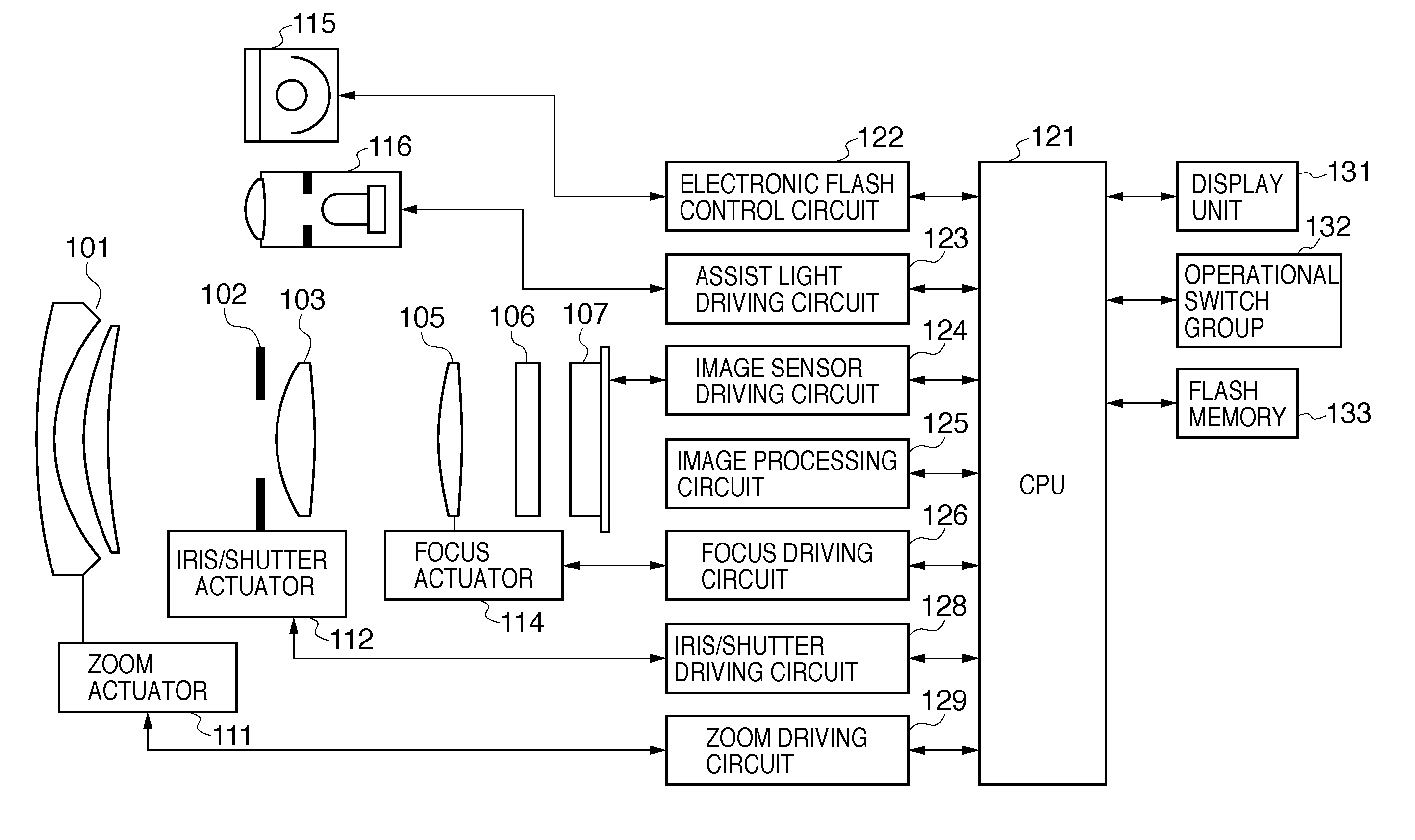
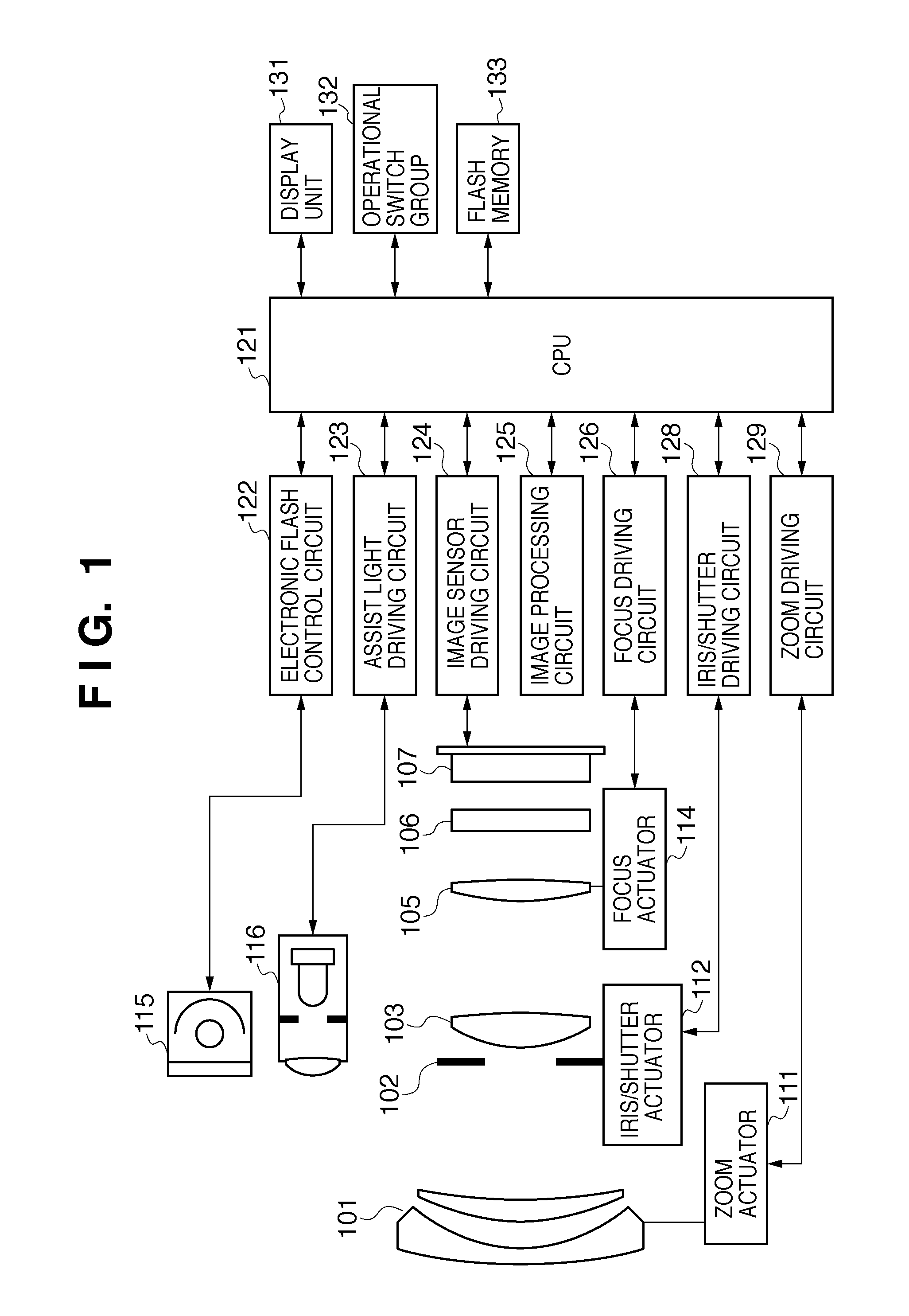
[0026]FIG. 1 is a diagram illustrating the configuration of a camera (image capturing apparatus) according to a first embodiment of the present invention, and illustrates a digital camera in which a camera body having an image sensor and an imaging lens are integrated in a single unit. In FIG. 1, 101 represents a first lens group arranged at the end of an imaging optical system (image formation optical system), the first lens group being held so as to be movable forward and backward in the optical axis direction. 102 represents an iris / shutter, and controlling the aperture diameter thereof enables the adjustment of the light amount during imaging; during still image capturing, the iris / shutter 102 also functions as an exposure time adjustment shutter. 103 represents a second lens group. The iris / shutter 102 and the second lens group 103 move backward and forward in the optical axis direction in unity, realizing a variable power effect (zoom function) by operating in tandem with the ...
second embodiment
[0052]FIG. 10 is a diagram illustrating operations according to a second embodiment, and is a variation on FIG. 9. In the present embodiment, the readout cycle is caused to be different depending on the focus detection row, and the accumulation time for focus detection pixels has been extended even further than in FIG. 9. FIG. 10 illustrates an example in which a single focus detection row is read out for every two frames of a moving image. The readout cycle of focus detection pixels may be determined as appropriate while referring to the output results of the focus detection pixels.
third embodiment
[0053]FIG. 11 is a diagram illustrating operations according to a third embodiment, and is a further variation on FIG. 9. The present embodiment describes an example in which the margin time T is insufficient during the live view, the capturing / recording of moving images, and so on, and switches, on a frame-by-frame basis, the focus detection rows to be read out. In FIG. 11, the readout from the focus detection rows V4 and V5 is switched to readout from the rows V10 and V11 from the third frame on; this makes it possible to move the focus detection rows without increasing the readout time.
PUM
 Abstract
Description
Claims
Application Information
PatSnap Eureka turns technology decisions into work you can execute. Powered by our Innovation Knowledge Graph, it runs expert workflows across engineering, life sciences, materials and intellectual property. Get your review-ready output in minutes.


