Organic el display panel and method of manufacturing the same
- Summary
- Abstract
- Description
- Claims
- Application Information
AI Technical Summary
Benefits of technology
Problems solved by technology
Method used
Image
Examples
embodiment 1
(Structure of Organic EL Display Panel 100)
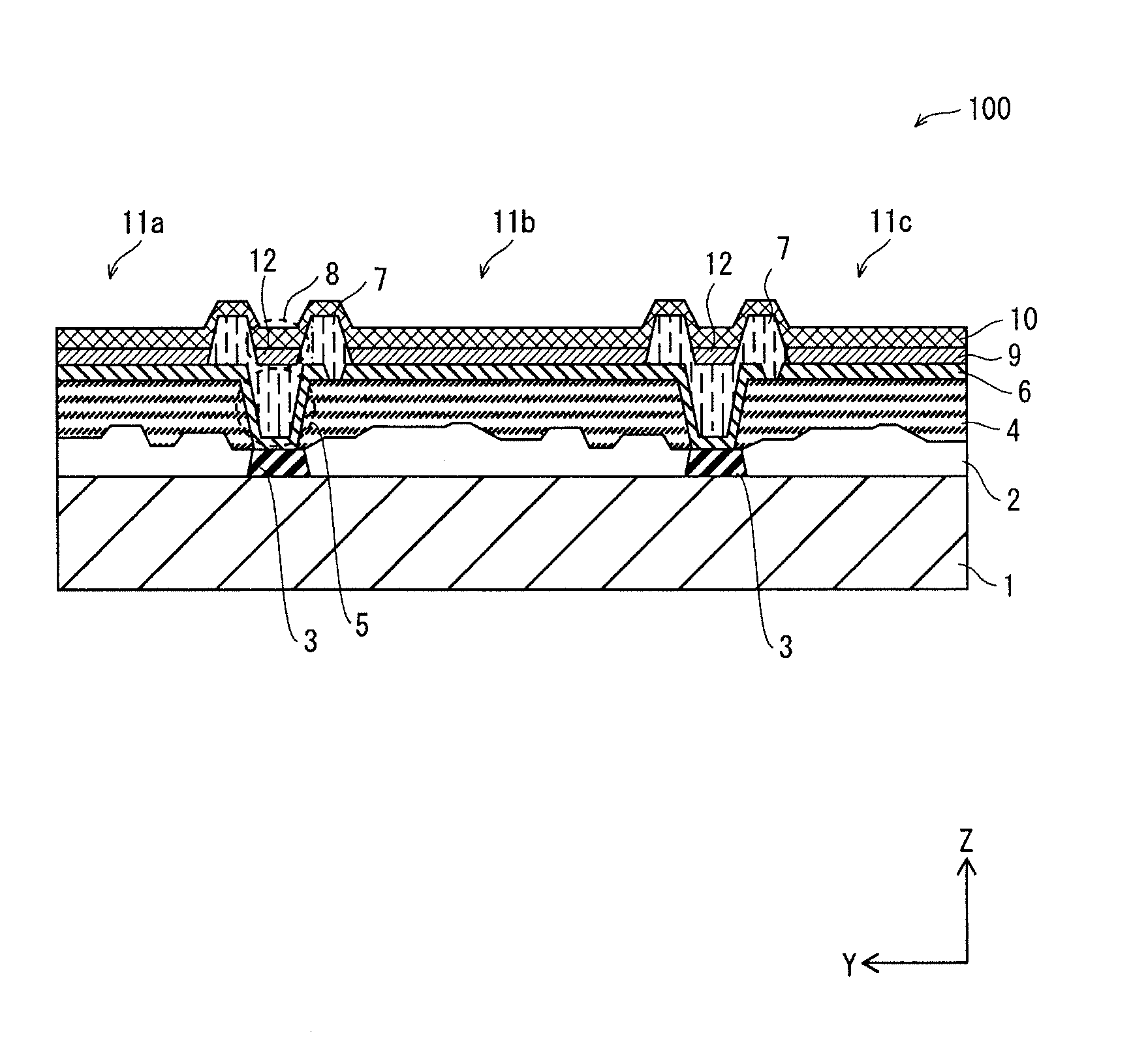
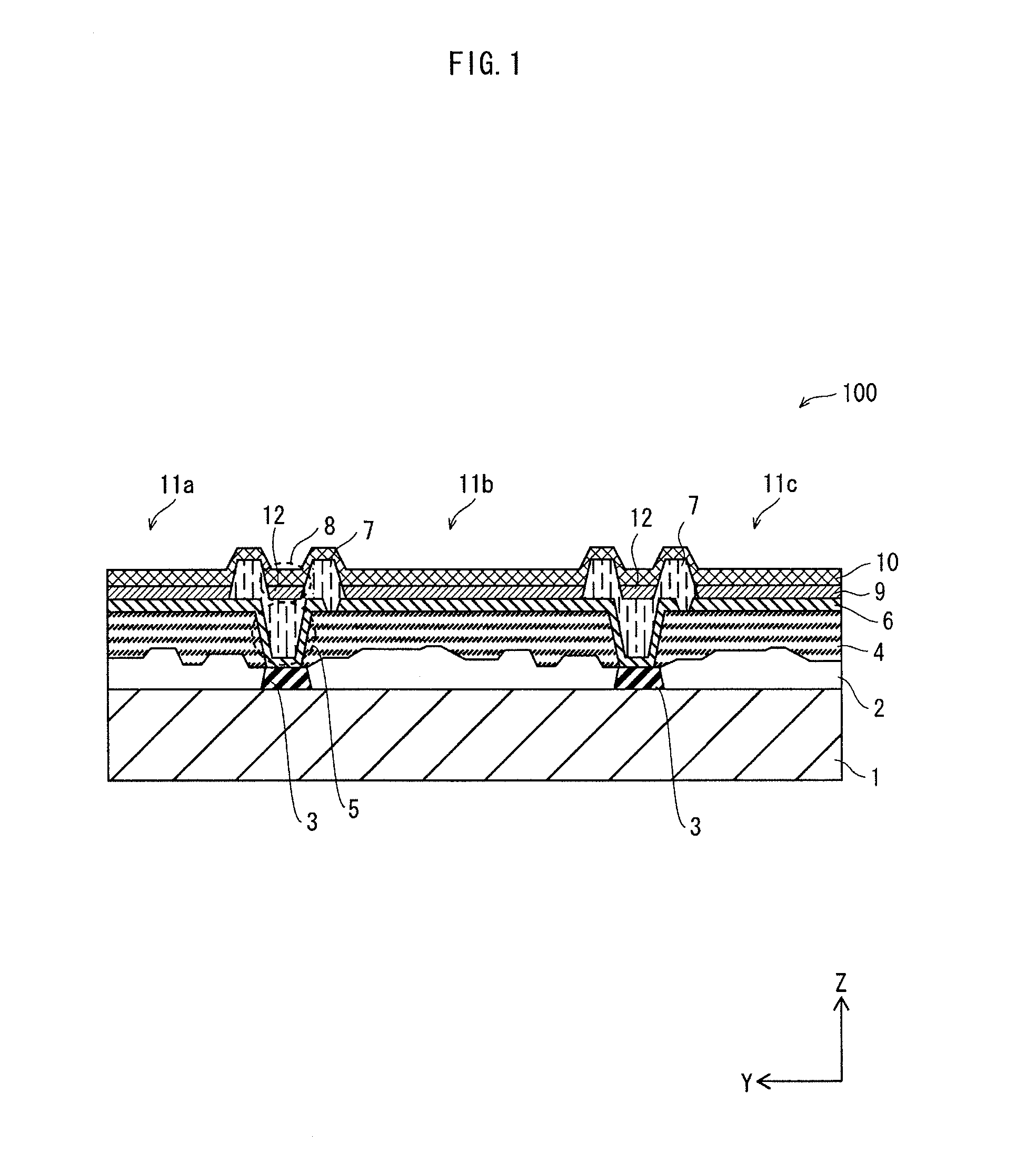
[0067]FIG. 1 is a cross-sectional view schematically showing the structure of an organic EL display panel 100 pertaining to Embodiment 1 of the present invention.
[0068]The organic EL display panel 100 shown in FIG. 1 includes, as subpixels (light-emitting pixels), organic EL elements 11a, 11b and 11c each having a light-emitting layer 9 corresponding to one of the following colors: R, G, and B. A combination of the three subpixels 11a, 11b and 11c constitutes one pixel. The organic EL elements 11a, 11b and 11c are adjacently arranged on an entirety of the organic EL display panel 100 in row (X) and column (Y) directions, i.e., in a matrix.
[0069]It goes without saying that the organic EL elements 11a, 11b and 11c may be configured to emit light of the same color.
[0070]On one main surface of a TFT substrate 1 (hereinafter, simply “substrate I”), a TFT wiring portion (TFT layer 2), a planarizing film 4, and a lower electrode 6 are layered in t...
embodiment 2
[0140]FIG. 12 is a schematic cross-sectional view showing the structure of an organic EL display panel 100A pertaining to Embodiment 2.
[0141]In the organic EL display panel 100A, a charge transport layer 9a is disposed beneath the light-emitting layer 9. The charge transport layer 9a improves luminous efficacy by suitably transporting a carrier toward the light-emitting layer 9. The charge transport layer 9a is formed in the wet process as with the light-emitting layer 9. More specifically, the charge transport layer 9a is formed by ejecting drops of ink containing a predetermined organic material (e.g., barium, phthalocyanine, lithium fluoride, or any combination of these materials) and solvent while maintaining the concentration of the vaporized solvent uniform along the column (Y) direction. This way, the charge transport layer 9a has a favorably uniform thickness. After the charge transport layer 9a is formed, the light-emitting layer 9 is formed thereon in the same manner as Em...
embodiment 3
[0144]FIG. 14 is a schematic cross-sectional view showing the structure of an organic EL display panel 100B pertaining to Embodiment 3.
[0145]In the organic EL display panel 100B, the contact holes 5 are not formed. Accordingly, the concaves 8 of the bank 7 are formed only through adjustment of the shape of the bank 7. Here, as shown in FIG. 15, the depth D3 of each concave 8 is adjusted to be the same as the height H of the bank 7. Alternatively, the depth D3 may be adjusted to be smaller than or larger than the height H.
[0146]In this structure also, the same drops of ink are ejected into the openings 13 and the concaves 8 in the wet process of the inkjet method during the step of forming the light-emitting layer 9. As a result, the concentration of the vaporized solvent is made uniform while the ink is being dried, and the light-emitting layer 9 having a uniform thickness is formed.
[0147]Furthermore, the nozzles 3030 in the inkjet head 30 are caused to eject the ink into the concav...
PUM
 Abstract
Description
Claims
Application Information
 - R&D
- Intellectual Property
- Life Sciences
- Materials
- Tech Scout
- Unparalleled Data Quality
- Higher Quality Content
- 60% Fewer Hallucinations
Browse by: Latest US Patents, China's latest patents, Technical Efficacy Thesaurus, Application Domain, Technology Topic, Popular Technical Reports.
© 2025 PatSnap. All rights reserved.Legal|Privacy policy|Modern Slavery Act Transparency Statement|Sitemap|About US| Contact US: help@patsnap.com


