Method for Operating a Reducing Agent Supply System

a technology of reducing agent and supply system, which is applied in the direction of engine components, mechanical equipment, machines/engines, etc., can solve the problems of unwanted expense, malfunctions, and the provision of third medium, so as to reduce the cross-section of the line system, increase the resistance to flow, and achieve the effect of measurable pressure increas

Inactive Publication Date: 2012-02-23
DAIMLER AG
View PDF8 Cites 2 Cited by
  • Summary
  • Abstract
  • Description
  • Claims
  • Application Information

AI Technical Summary

Benefits of technology

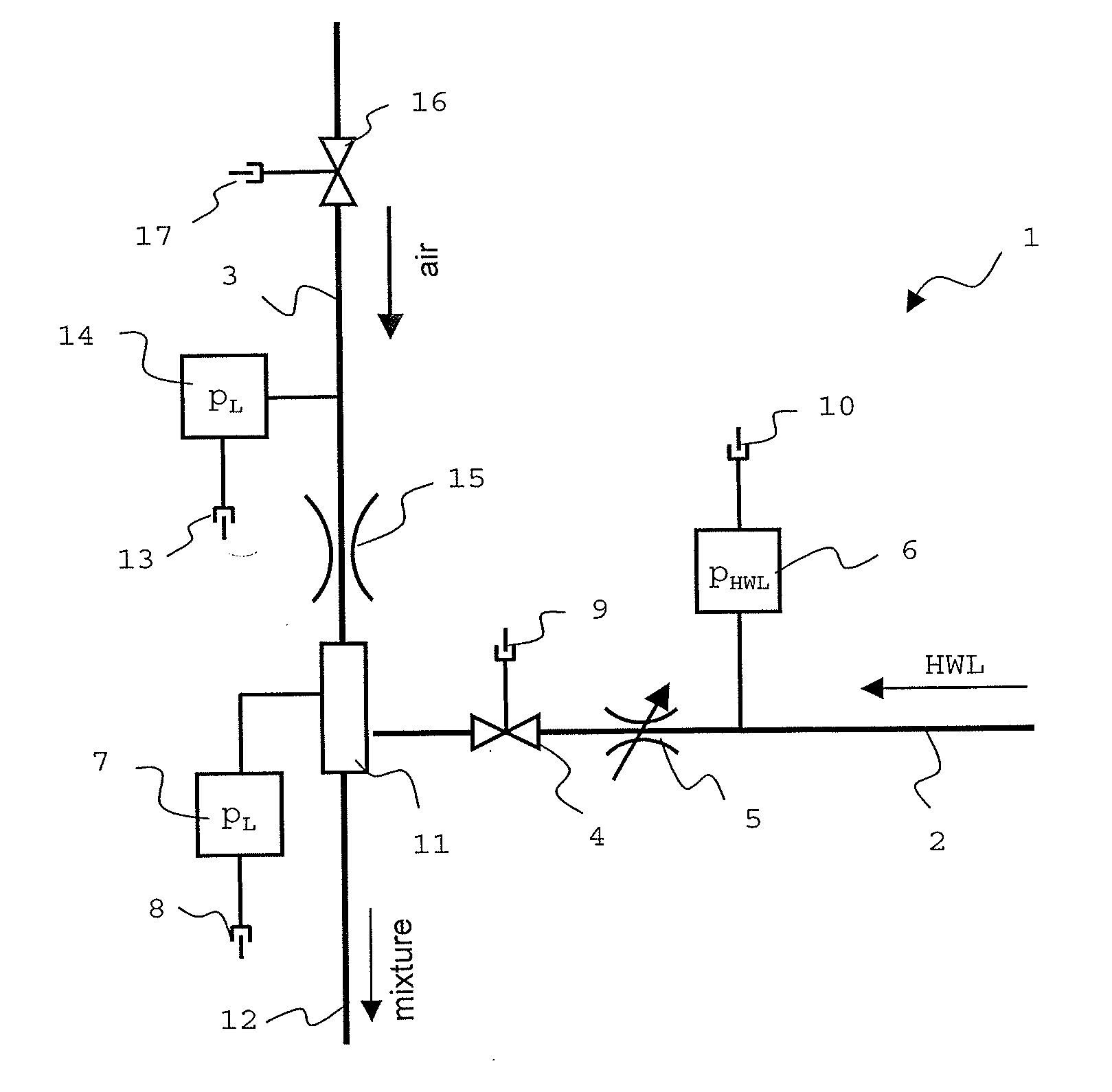
[0008]In one embodiment of the method, a back pressure in a line of the reducing agent supply system for transporting the air stream to the nozzle is determined and the cleaning operation is activated upon exceeding a pre-settable, in particular first, upper pressure threshold value. Reliable monitoring of the reducing agent supply system, in particular with regard to deposits and other contaminants having the effect of constricting the cross-section in the line system, is made possible due to preferably continuous pressure monitoring. For example, deposits due to corrosion or alternatively urea deposits in the line system through which air flows of the reducing agent supply system result in an increased resistance to flow. In the case of an air stream of known or pre-settable size which is preferably used, this results in a measurable pressure increase. By monitoring the back pressure at a pre-set suitable point in the line system, preferably in a line through which air and/or HWL/air mixture can flow, it can thus be reliably determined whether there is a need for cleaning of the reducing agent supply system. If an impermissible increase in the back pressure is detected, the cleaning operation is activated.
[0009]Analogously, in a further embodiment of the method, a back pressure in a line of the reducing agent supply system for transporting the air stream to the nozzle is determined and an activated cleaning operatio

Problems solved by technology

One problem of such methods is that malfunctions can be caused due to deposits of urea in the correspondi

Method used


Image

  • Method for Operating a Reducing Agent Supply System
  • Method for Operating a Reducing Agent Supply System
  • Method for Operating a Reducing Agent Supply System

Examples


Embodiment Construction

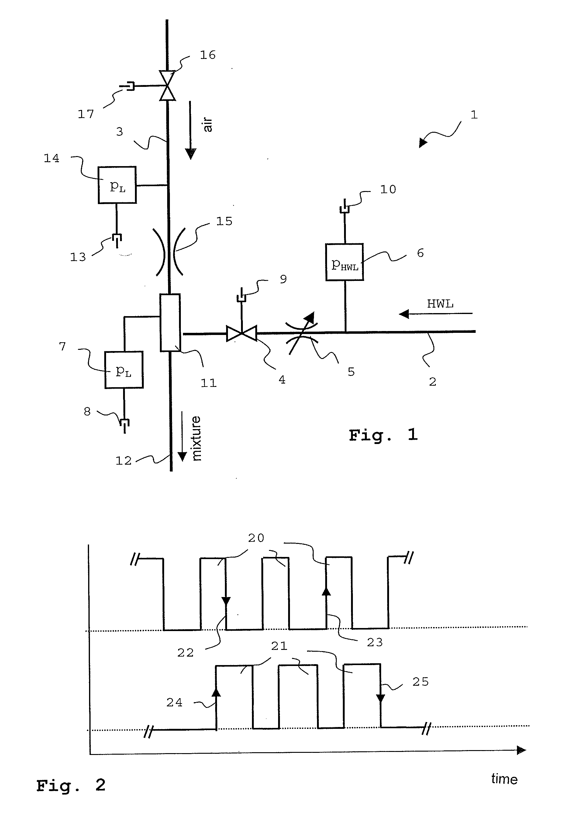
[0019]In the advantageous embodiment diagrammatically illustrated in FIG. 1, a reducing agent supply system 1 comprises a liquid supply line 2 for a liquid that is to be metered. A metering valve 4, which can be operated in timed manner, and an adjustable adjusting choke 5, a first pressure sensor 6 are arranged in the liquid supply line 2. The liquid supply line 2 opens, as does an air supply line 3 for supplying compressed air, into a mixing region 11 of the reducing agent supply system 1. In the mixing region 11, thorough mixing of supplied compressed air and liquid takes place such that an aerosol-like mixture with liquid droplets are produced that are as small as possible. The mixing region 11 may be formed as a separate mixing chamber or as an integral component of the liquid supply line 2 or the air supply line 3.

[0020]Below, it will be assumed that the liquid is an aqueous urea solution (HWL), which can be sprayed in the form of the aerosol-like mixture by means of a nozzle ...


PUM


Abstract

A method for operating a reducing agent supply system for supplying an exhaust aftertreatment system of a motor vehicle is provided. In normal metering operation of the reducing agent supply system an at least approximately continuous air stream and a pulsed reducing agent stream are produced and are released at least partially via the nozzle into the exhaust line. In a cleaning operation for cleaning the reducing agent supply system an air stream formed from a number of air stream pulses and a reducing agent stream formed from a number of reducing agent stream pulses are produced and supplied to the nozzle means. The method can be used in particular in supply systems in which aqueous urea solution is used as reducing agent.

Description

BACKGROUND AND SUMMARY OF THE INVENTION[0001]The invention relates to a method for operating a reducing agent supply system a reducing agent supply system for supplying an exhaust aftertreatment system of a motor vehicle with a reducing agent serving for emission control, in which an air stream and a reducing agent stream are supplied to a nozzle which opens into an exhaust line.[0002]In order to reduce nitrogen oxides in the exhaust of internal combustion engines, in particular of motor vehicle diesel engines, it is known to add aqueous urea solution to the exhaust. In the hot exhaust, ammonia is released which, as a selectively operating reducing agent, renders nitrogen oxides harmless by reduction at a selective catalytic reduction (SCR) catalyst. The urea solution is frequently, by means of compressed air support, supplied to the exhaust in atomized form as an aerosol. One problem of such methods is that malfunctions can be caused due to deposits of urea in the corresponding red...

Claims


Application Information

Patent Timeline
IPC IPC(8): F01N3/18
CPCF01N2610/08Y02T10/47Y02T10/24F01N3/208F01N2610/02F01N2610/146F01N11/00F01N2900/1824F01N2900/1808F01N2550/05F01N2610/1493Y02A50/20Y02T10/12Y02T10/40
Inventor HOCHHOLZNER, MICHAELBAIER, HORSTWANDEL, RALF
Owner DAIMLER AG
Why Eureka
Try Eureka