Pipe joints

a pipe joint and pipe technology, applied in the direction of hose connection, other domestic objects, mechanical equipment, etc., can solve the problems of unsatisfactory joint bond, potential contamination source, residual adhesive cement not satisfactorily adhering to the two surfaces,

Active Publication Date: 2012-02-23
IPS WELD ON DIV
View PDF10 Cites 31 Cited by
  • Summary
  • Abstract
  • Description
  • Claims
  • Application Information

AI Technical Summary

Benefits of technology

[0025]The joint is fully formed when the extrudable adhesive has changed to a solid material that substantially fills the coaxial space and the opposing channels forming a retaining ring. The solid adhesive material serves as a retaining ring as well as the adherent for the adhered pipes. Mechanistically, the retaining ring and adhered pipes share the shear stress on the joint when the joint is pressurized, thusly assuring that even under conditions where there would be adhesive shear failure, the pipes may still remain joined, and the joint would continue to sealedly function.
[0026]As previously discussed the unadhered pre-assembled joint is held in position by a compressing apparatus, that aligns and positions the elements of the pipe joint in compression. The compressed unadhered pre-assembled joint has ports that are in fluid communication with the distribution channel and the coaxial cavity that is to receive the extruded adhesive. Typically, after being pre-assembled, the coaxial cavity of the unadhered pre-assembled joint contains an ambient fluid, typically air, but in the case of underwater assembly, water would be the ambient fluid, and in the case of assembly in outer-space the ambient fluid would be defined by the ambient conditions in outer-space. The extruded adhesive is typically pumped by an extruder into the coaxial cavity of the una

Problems solved by technology

When olefinic pipes, such as those previously described, are attempted to be adhered in a similar fashion, the joint bond is unsatisfactory.
The low surface energy olefinic plastics are resistant to solvent etching, and the residual adhesive cement does not satisfactorily adhere the two surfaces.
The inward bead can actually

Method used


Image

  • Pipe joints
  • Pipe joints
  • Pipe joints

Examples


Embodiment Construction

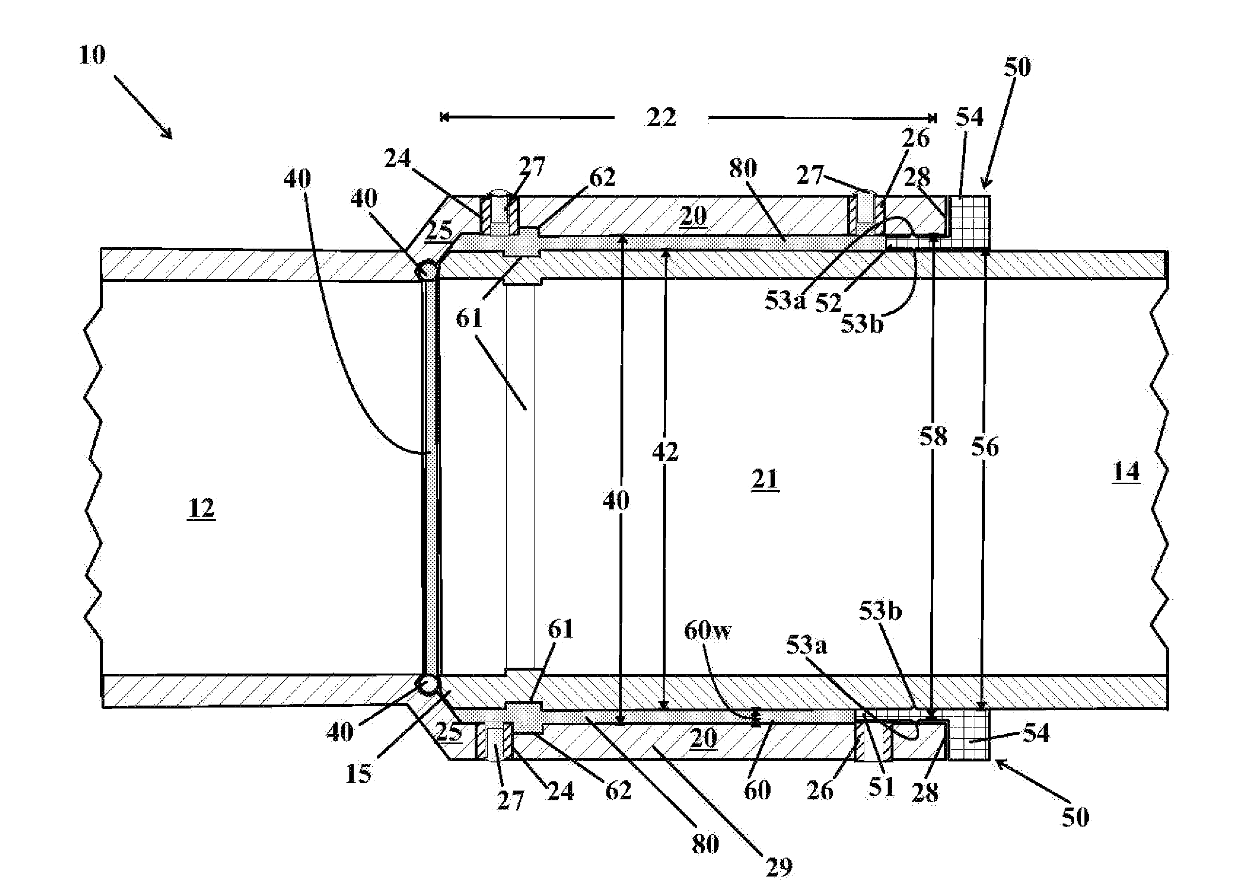
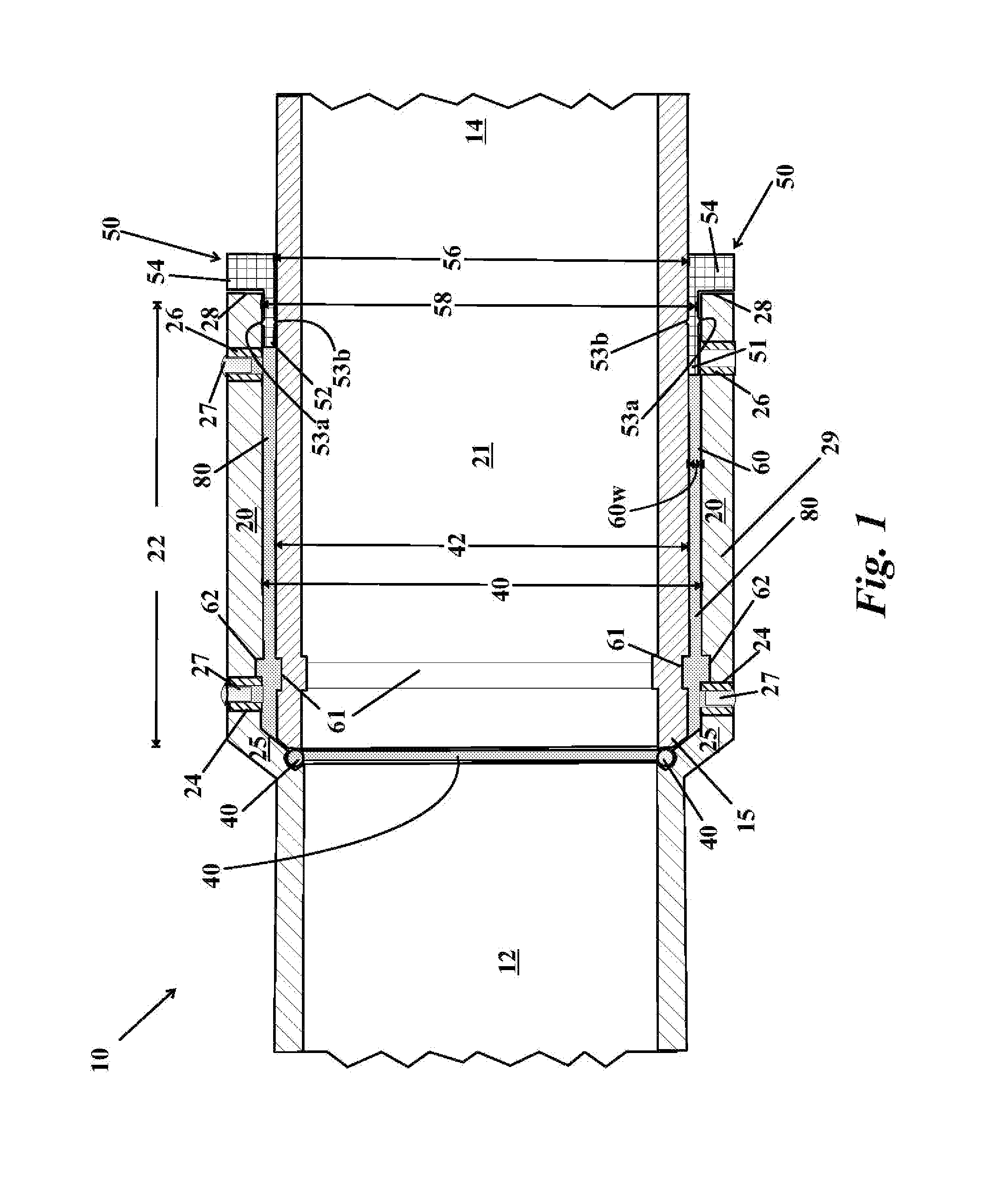
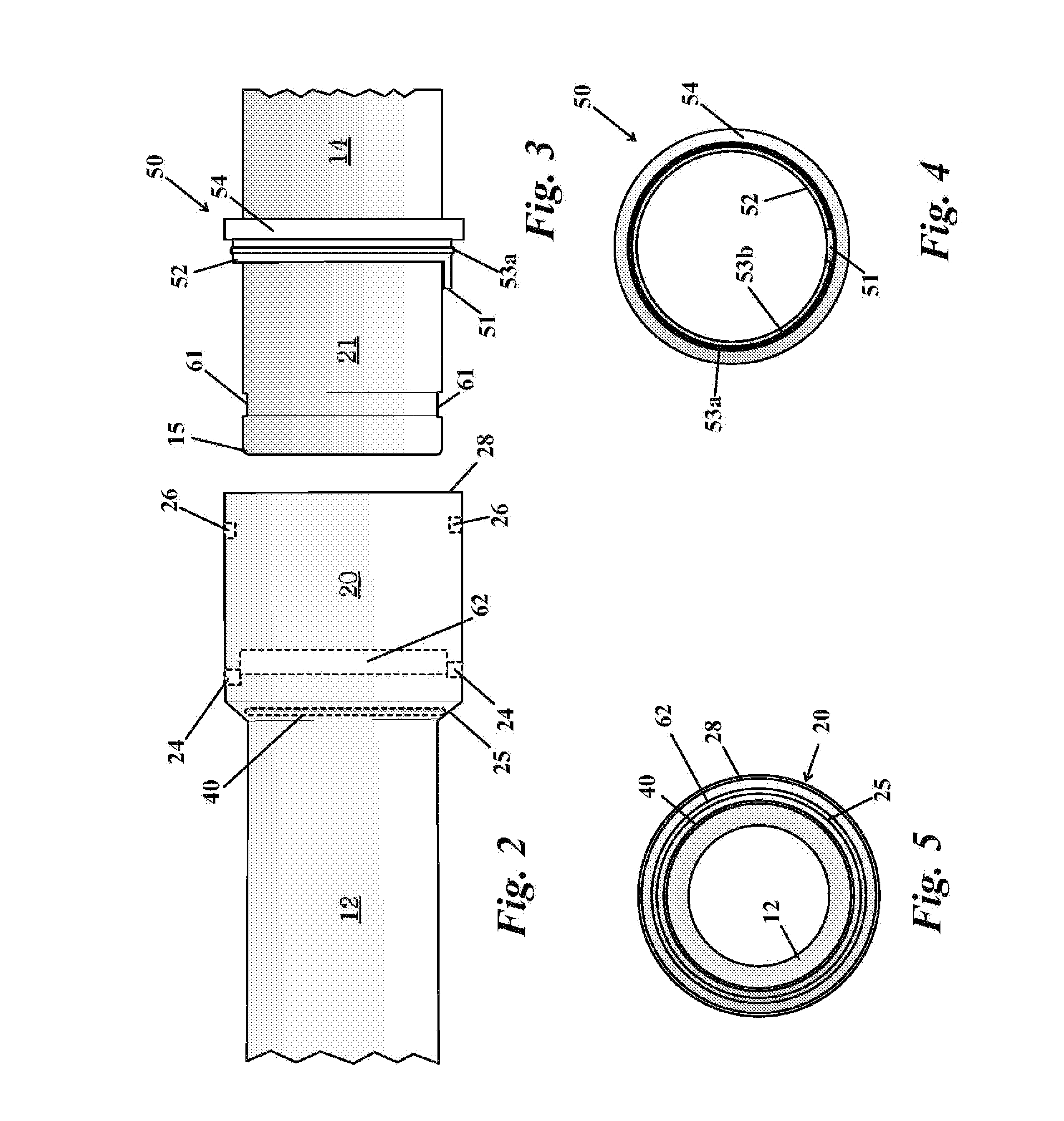
[0042]The invention, as illustrated in the drawings is an adhesively connected pipe joint 10. Referring to the longitudinal cross-sectional view shown in FIG. 1, an illustrated embodiment of the joint 10 has a first pipe 12 with an enlarged end section that is a socket 20. The socket 20 is substantially cylindrical in shape. The socket 20 has a self-centering bottom 25 having a seated gasket / o-ring 40 and an opening mouth having a rim 28. The socket 20 has a length 22 as measured from the rim 28 to the bottom 25, where the bottom is slanted to induce self-centering. The length 22 is substantially a cylindrical wall 29 having elements that determine an adhesive bond line between the socket 20 and a second pipe 14. The socket 20 has a plurality of ports 24,26. Ports closest to the bottom 25 are numbered 24, and ports closest to the rim 28 are numbered 26. As is evident from the drawing, an inside diameter 40 of the socket 20 is greater than the outside diameter 42 of an insertion sect...


PUM

PropertyMeasurementUnit
Fractionaaaaaaaaaa
Angleaaaaaaaaaa
Thicknessaaaaaaaaaa

Abstract

The invention is a pipe joint for joining pipes composed of materials that are difficult to adhere. The major elements are an extrudable adhesive; a first pipe having a socket with an inside diameter, where said socket has a mouth, a self-centering bottom with a gasket, a cylindrical wall with a plurality of ports, and an inner annular channel. A second pipe has an insertion section with an squared-off end and a rolled groove. The second pipe having an outside diameter that is less than the inside diameter of the socket, where the difference defines a coaxial cavity with a width. The rolled groove serves as a distribution channel while the adhesive is a liquid, and upon curing the solid adhesive functions as a retaining ring. A flanged annular ring, potentially aided by a compression apparatus, caps the cavity, centers the insertion section, and maintains compression. The adhesive includes alkyl-borane-adhesives.

Description

CROSS REFERENCE TO RELATED PATENT APPLICATION[0001]This application is a continuation-in-part of currently pending patent application Ser. No. 12 / 045,565 filed on Mar. 10, 2008, which is a divisional application stemming from patent application Ser. No. 11 / 089,222 filed on Mar. 24, 2005 and issued on Mar. 11, 2008 as U.S. Pat. No. 7,341,285. Patent application Ser. No. 11 / 089,222 claimed the benefit of the priority filing date of the provisional patent application Ser. No. 60 / 555,923, originally filed on Mar. 24, 2004; and the continuation-in-part application also claims the benefit of the original filing date of Mar. 24, 2004.BACKGROUND OF THE INVENTION[0002]1. Field of the Invention[0003]The mention relates generally to a method for joining pipes, and more particularly to a method and a system for joining pipes comprised of low surface energy materials, such as HDPE (high density polyethylene), PEX (cross linked polyethylene), and PVDF (polyvinylidene difluoride). Low energy surfa...

Claims


Application Information

Patent Timeline
IPC IPC(8): F16L13/11F16L21/02F16L55/00
CPCB29C65/542B29C65/484B29C65/7814B29C65/7832B29C65/7835B29C66/1222B29C66/1226B29C66/342B29C66/5221B29C66/5229B29C66/55B29C66/81B29C66/8223B29C66/8286B29K2023/065B29K2023/0691B29K2027/16F16L13/116F16L47/02B29C65/665B29C65/485B29C65/483B29C65/4815B29C66/52298B29C66/52291B29C66/52292B29K2023/12B29K2027/18B29C65/362B29C65/368B29C66/71B29C65/7841B29L2031/7172B29K2083/00B29K2055/02B29K2033/08B29K2031/04B29K2027/08B29K2027/06B29K2023/16B29K2023/06
Inventor MCPHERSON, TERRY R.
Owner IPS WELD ON DIV
Why Eureka
Try Eureka