Systems and Methods for Power Demand Management

a power demand management and power demand technology, applied in the field of power storage technology, can solve the problems of large strain on transmission and production facilities, inconvenient maintenance of spare generating capacity, and difficulty in adding extra generating capacity, so as to reduce consumption, improve the effect of power demand measurement, and reduce the cyclical nature of electricity demand

Inactive Publication Date: 2012-02-23
POWERMAESTRO
View PDF21 Cites 42 Cited by
  • Summary
  • Abstract
  • Description
  • Claims
  • Application Information

AI Technical Summary

Benefits of technology

[0011]A transformation of the power grid in the United States and other countries to a more efficient system has already begun—the so-called “Smart Grid” transformation or revolution. In order to better measure power demand, several utilities have begun installing electronic power consumption meters (“smart meters” in their customers' facilities. Smart meters will eventually allow for (i) measurement of power consumption in real-time or near real-time and (ii) “dynamic pricing”, i.e., adjustment of pricing of the electricity consumed based at least in part on an aggregate measure of power consumption across a segment of customers, e.g., the buildings in a particular United States zip code. As the Smart Grid revolution progresses, consumers face high electricity prices during peak demand periods. However, many of these consumers may not want the inconvenience of monitoring their electric energy consumption so as to reduce consumption during peak demand periods by turning off some of the loads in their buildings. Therefore, consumers desire a means for addressing the dynamic pricing of electricity to avoid high electricity prices during peak demand periods. This means would preferably not burden the consumer with continuous monitoring of their electricity consumption.
[0012]The methods, systems, and devices described herein address these and other needs. According to one aspect of the invention, a system and method for distributing cyclical power demand is provided, by drawing on locally-stored energy during periods of high electricity demand. Local energy storage systems that allow the operating of electrical equipment even in the event of a power or grid outage are desirable for consumers for many reasons, such as for the operation of life support equipment or to provide heating and cooling in regions with extreme conditions. By charging local energy storage systems during periods of low demand and using the locally-stored energy to power appliances during periods of high demand, the cyclical nature of electricity demand can be alleviated—from the perspective of both consumers and the utilities that supply these consumers with electricity.
[0013]For example, if a thousand homes each had local energy storage capability of about two kilowatt-hours at peak demand periods (which may last 3-4 hours), the load on the grid may be reduced by as much as two megawatt-hours during the peak demand period. For most utilities, this may be a significant amount of power and the reduction in load in this manner during those peak demand periods could prevent a brownout or blackout from occurring.

Problems solved by technology

The sheer amount of electricity that must be generated and transported to consumers places a large strain on transmitting and production facilities.
However, since electricity demand is cyclical, it is not cost-efficient to maintain spare generating capacity (e.g., an additional power generating plant) that is only used periodically.
Moreover, as total electricity demand continues to rise, adding extra generating capacity becomes difficult, due to community and political resistance toward constructing power-generating facilities—both in terms of the location of additional power generating plants and additional transmission and distribution power lines.
As the Smart Grid revolution progresses, consumers face high electricity prices during peak demand periods.
However, many of these consumers may not want the inconvenience of monitoring their electric energy consumption so as to reduce consumption during peak demand periods by turning off some of the loads in their buildings.

Method used


Image

  • Systems and Methods for Power Demand Management
  • Systems and Methods for Power Demand Management
  • Systems and Methods for Power Demand Management

Examples


Embodiment Construction

[0022]To provide an overall understanding of the invention, certain illustrative embodiments will now be described, including systems and methods for power demand leveling. However, it will be understood by one of ordinary skill in the art that the systems and methods described herein may be adapted and modified for other suitable applications and that such other additions and modifications will not depart from the scope thereof.

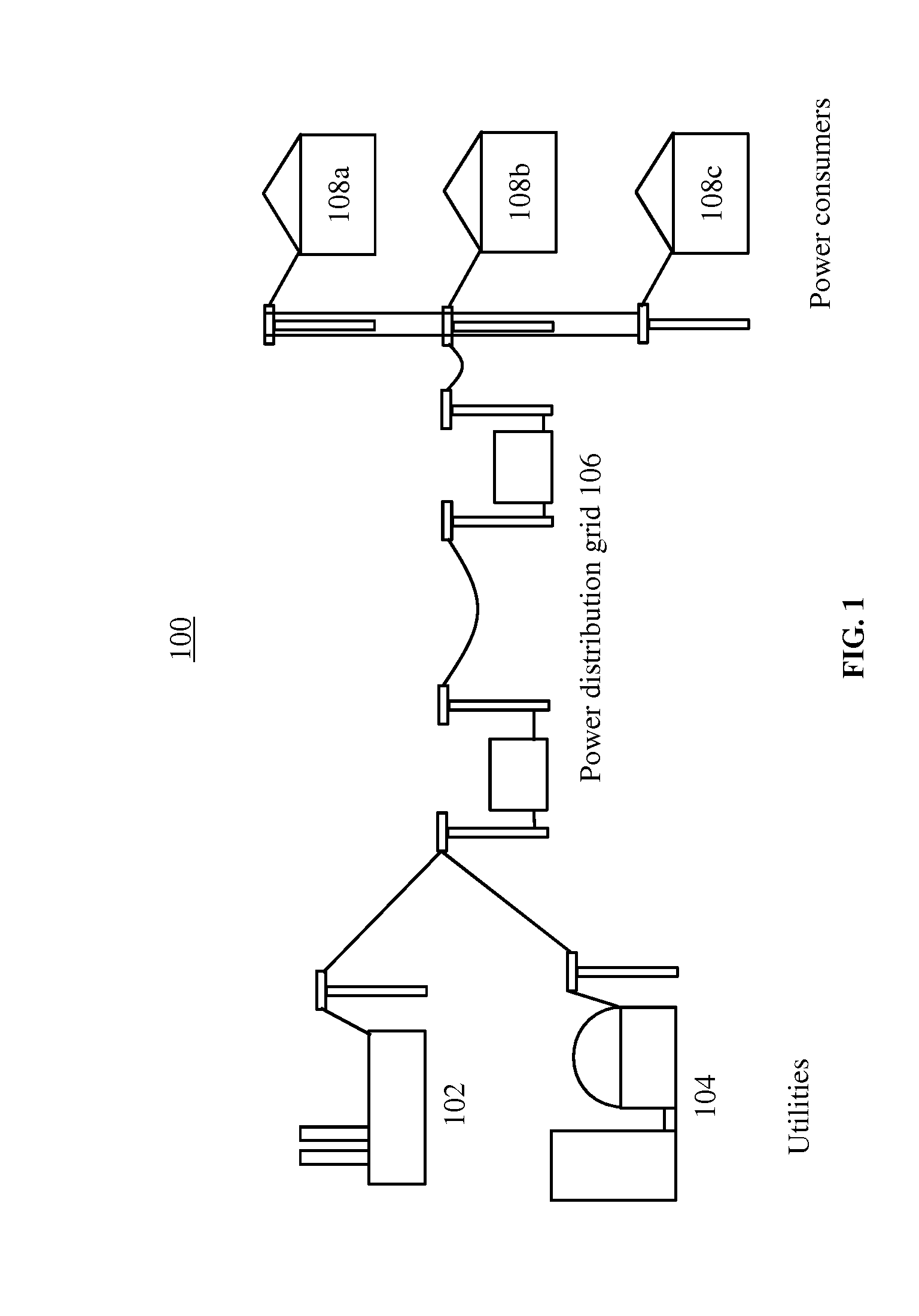
[0023]FIG. 1 depicts a system 100 for distributing power between power generators such as utilities and power consumers. Utilities 102 and 104, each of which generate power for sale to consumers, are linked to a power distribution grid 106. Power consumers 108a-d are also linked to the power distribution grid 106, and may receive 2 power generated by utility 102 and / or utility 104. Power consumers may be residential households, commercial properties, industrial operations, or any entity that uses electric power.

[0024]While two utilities and four power consum...


PUM


Abstract

A system and method for shifting power load on a power distribution network with multiple power loads, each of which draws power from the power distribution network. The system includes a controller communicatively coupled to an energy storage system and power load on the power distribution network. The controller is configured to receive a load-shifting signal, determine a load-shifting procedure, and switch one or more of the communicatively coupled power loads from drawing power from the power distribution network to drawing power from the energy storage system according to a load-shifting algorithm.

Description

CROSS-REFERENCE TO RELATED APPLICATION[0001]Provisional Application No. 61 / 375,130BACKGROUND OF THE INVENTION[0002]1. Field of the Invention[0003]This invention relates generally to the use of power storage technology to provide extended electrical energy backup to systems and appliances in the home when the electric power grid is not operational. More specifically, it relates to a system that allows a homeowner to select which systems and appliances should be connected to a power backup system then provides such power backup from a source other than a generator until the power from the electrical grid is restored or the allocated backup power is exhausted.[0004]2. Description of the Related Art[0005]When the electric grid is unable for any reason to provide electrical power to peoples' homes, then many critical home systems and appliances are unable to operate until such power is restored. Extended grid outages result in severe hardships for individuals, whether they occur in a nor...

Claims


Application Information

Patent Timeline
Patent Type & Authority Applications(United States)
IPC IPC(8): G06F1/30G06F1/26
CPCH02J3/32H02J9/062H02J13/0075Y02B70/3291Y02B90/222Y02E60/722Y04S20/12Y04S20/248Y04S10/30Y02E60/74Y04S10/14H02J13/00002H02J13/00024H02J13/00026Y02B70/30Y02B90/20Y02E60/00
Inventor ORTHLIEB, FREDERICK L.LETZT, ALAN M.
Owner POWERMAESTRO
Why Eureka
Try Eureka