Damping force control apparatus

a technology of damping force and control apparatus, which is applied in the direction of bicycle equipment, instruments, transportation and packaging, etc., can solve the problems of difficult control of damping force, degradation of riding quality, and worsening riding quality, so as to improve riding quality, improve riding quality, and suppress degradation of riding quality

Inactive Publication Date: 2012-02-23
TOYOTA JIDOSHA KK
View PDF8 Cites 6 Cited by
  • Summary
  • Abstract
  • Description
  • Claims
  • Application Information

AI Technical Summary

Benefits of technology

[0010]Therefore, as can be understood from the foregoing, the aim of setting the linear damping coefficient Cs differs depending on the purpose of the control. For this reason, it is difficult to control the damping force in a manner that both improves the damping performance of the sprung member and suppresses degradation in the riding quality when intermediate / high-frequency vibrations are inputted.
[0011]Having been achieved to address the aforementioned problem, it is an object of the present invention to provide a damping force control apparatus capable of quickly dampening vibrations in the sprung member and capable of suppressing a degradation in a riding quality when an intermediate / high-frequency vibration has been inputted.
[0013]According to the present invention, the variable damping coefficient is calculated so as to suppress vibrations in the sprung member by applying the nonlinear H-infinity control theory to the control system designed based on the motion of the suspension apparatus. Furthermore, the linear damping coefficient can be determined so as to be lower as a value representing a vibration having the frequency within the specific frequency band set in advance which is greater than the sprung member resonation frequency (such as the acceleration of the vibration having the frequency within the specific frequency band) is greater.
[0014]Therefore, when the vibration having the frequency within the specific frequency band inputted into the suspension apparatus is low, or when no vibration having the frequency within the specific frequency band is inputted, the linear damping coefficient is set to a high value. As a result, the requested damping force calculated based on the variable damping coefficient and the linear damping coefficient also increases, and thus vibrations in the sprung member are quickly dampened. However, in the case where the inputted vibration having the frequency within the specific frequency band is great, the linear damping coefficient is set to a low value. This reduces the requested damping force. The specific frequency band is a frequency band that is higher than the sprung member resonation frequency, and thus vibrations having the frequency within the specific frequency band are intermediate / high-frequency vibrations. In other words, when the intermediate / high-frequency vibrations are great, the requested damping force decreases. This makes it possible to suppress degradation in the riding quality when an intermediate / high-frequency vibration is inputted, and makes it possible to suppress degradation in the riding quality particularly when the vibration speed is high. In this manner, the damping force control apparatus according to the present invention changes the magnitude of the linear damping coefficient in accordance with the magnitude of the value representing an inputted vibration having the frequency within the specific frequency band, and thus vibrations in the sprung member can be quickly dampened and a degradation in the riding quality when vibrations having the frequency within the intermediate / high frequency band are inputted.
[0027]Through this, vibrations generated by vertical (heave) motion, roll motion, and pitch motion (these vibrations are generally low-frequency vibrations) in a control target location of the sprung member are effectively dampened by applying the nonlinear H-infinity control theory to the control system designed based on the motion of the four suspension apparatuses expressed by the four-wheel vehicle model. Furthermore, a damping force for vibrations caused by the stated three types of motion can be ensured by the variable damping force, and the riding quality can be improved for inputted vibrations having the frequency within the specific frequency band by the linear damping force. Accordingly, low-frequency vibrations caused by the stated three types of motion can be dampened, and degradation in the riding quality can also be suppressed when vibrations having the frequency within the specific frequency band (the intermediate / high-frequency band) are inputted. Furthermore, because the linear damping coefficient changes so as not to affect the roll motion and pitch motion of the sprung member, the riding quality can be further improved.

Problems solved by technology

However, if a vibration having the frequency greater than the sprung member resonation frequency, particularly the frequency between the sprung member resonation frequency and an unsprung member resonation frequency (approximately 11 Hz) (so called “intermediate frequency”) is inputted into the suspension apparatus during damping control of the sprung member, the riding quality instead worsens as the damping force is increased.
The degradation of the riding quality is particularly noticeable with high vibration speeds.
For this reason, it is difficult to control the damping force in a manner that both improves the damping performance of the sprung member and suppresses degradation in the riding quality when intermediate / high-frequency vibrations are inputted.

Method used


Image

  • Damping force control apparatus
  • Damping force control apparatus
  • Damping force control apparatus

Examples


first embodiment

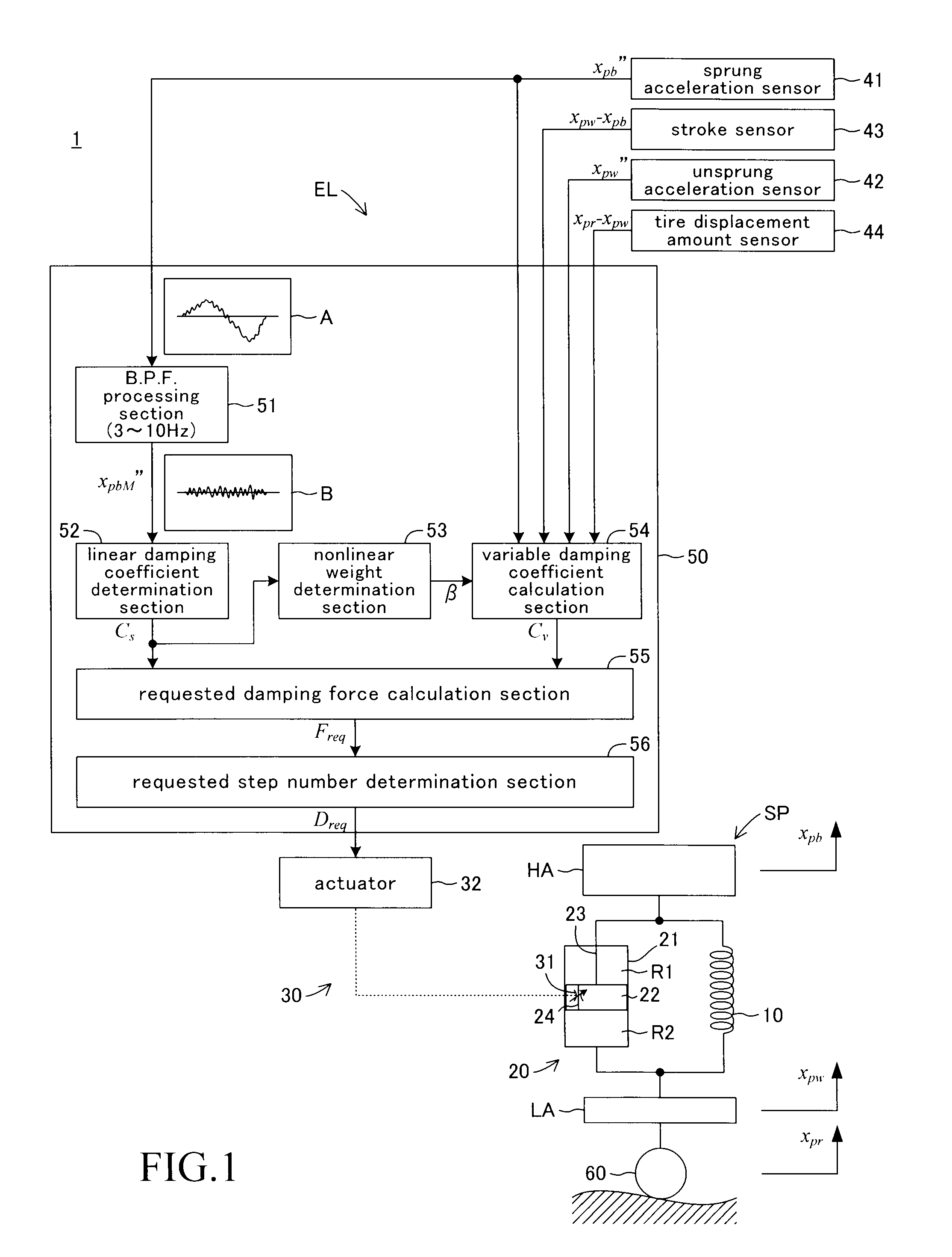
[0056]FIG. 1 is a general diagram illustrating an overall vehicle suspension control apparatus according to a first embodiment of the present invention. As shown in FIG. 1, a suspension control apparatus 1 includes a suspension apparatus SP and an electric control apparatus EL.

[0057]Four suspension apparatuses SP are attached to the vehicle, at the left-front, right-front, left-rear, and right-rear thereof, and each suspension apparatus SP includes a spring 10 and a damper 20. The spring 10 and the damper 20 are interposed between a sprung member HA and an unsprung member LA of the vehicle, with one of the ends (the lower end) of the spring 10 and the damper 20 being connected to the unsprung member LA and the other of the ends (the upper end) of the spring 10 and the damper 20 being connected to the sprung member HA. In the present embodiment, the spring 10 is a coil spring. This spring is a vibrating body having a predetermined spring constant. The damper 20 is disposed so as to b...

second embodiment

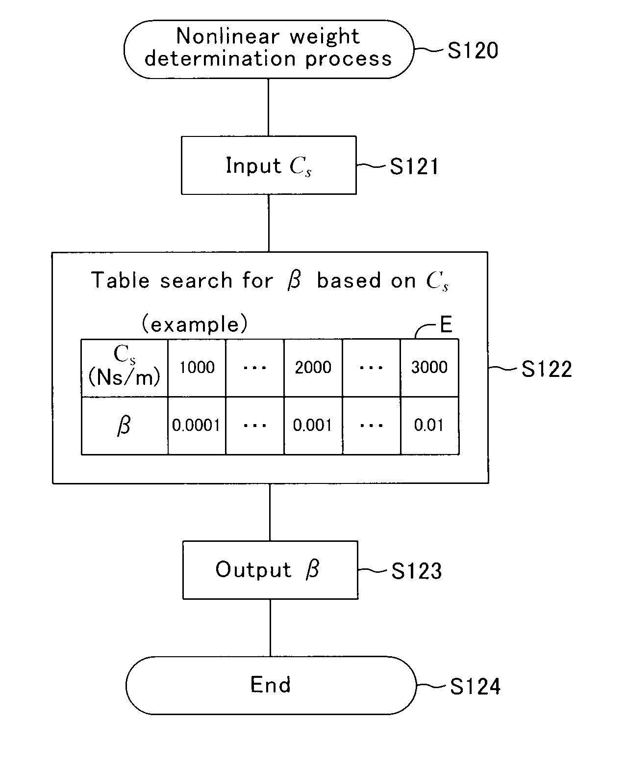
[0109]In the aforementioned first embodiment, the damping force is controlled so that the Lissajous curve expressing the transition of the requested damping force Freq falls within the range of variation R for the damping force characteristic of the damper 20, by changing the value of the nonlinear weight β in accordance with the magnitude of the linear damping coefficient Cs. However, in the present embodiment, the requested damping force is corrected so that the requested damping force falls within the range of variation for the damping force characteristic of the damper in accordance with changes in the linear damping coefficient Cs.

[0110]FIG. 13 is a general diagram illustrating an overall vehicle suspension control apparatus according to a second embodiment of the present invention. A suspension control apparatus 2 includes a suspension apparatus SP and an electric control apparatus EL. The electric control apparatus EL includes various types of sensors and a microcomputer 150....

third embodiment

[0147]Next, a third embodiment of the present invention will be described. The damping force control apparatus described in the present embodiment simultaneously controls the damping forces generated by the dampers in respective four suspension apparatuses so as to dampen vibrations in control target locations of the sprung member HA caused by heave motion (vertical motion), roll motion, and pitch motion in the sprung member HA, by applying the nonlinear H-infinity control theory to a control system designed based on the motion of four suspension apparatuses attached to the left- and right-front and left- and right-rear of the sprung member HA.

[0148]FIG. 19 is a diagram illustrating a vehicle model (a four-wheel model) in which four suspension apparatuses SPFR, SPFL, SPRR, and SPRL are attached to the sprung member HA at the left- and right-front and left- and right-rear thereof. As shown in the diagram, the suspension apparatus SPFR is attached to the right-front location of the sp...


PUM


Abstract

The magnitude of a linear damping coefficient Cs is set so as to decrease the greater a maximum amplitude value α of an intermediate frequency sprung acceleration is. In the case where a damping force control apparatus carries out control for dampening vibrations of a sprung member using a nonlinear H-infinity control theory, the linear damping coefficient Cs is set to a high value when the maximum amplitude value α of the intermediate frequency sprung acceleration inputted to a suspension apparatus is low. Accordingly, a requested damping force Freq also increases, which makes it possible to quickly dampen vibrations in the sprung member. Meanwhile, in the case where the maximum amplitude value α of the intermediate frequency sprung acceleration is high, the linear damping coefficient Cs is set to a low value. Accordingly, the requested damping force Freq also decreases, which makes it possible to suppress degradation in the riding quality when intermediate frequency vibrations are inputted, and particularly makes it possible to suppress riding quality degradation when the vibration speed is high.

Description

BACKGROUND OF THE INVENTION[0001]1. Technical Field[0002]The present invention relates to damping force control apparatuses that control damping forces in vehicle suspension apparatuses.[0003]2. Related Art[0004]Vehicle suspension apparatuses include dampers and springs interposed between an sprung member (above-spring member) such as a vehicle body and unsprung members (below-spring members) such as lower arms linked to wheels. Suspension apparatuses configure a vibration system. Furthermore, suspension apparatuses function so as to dampen vibrations of the sprung member by damping forces generated by the dampers.[0005]Damping force control apparatus, which controls the damping forces generated by the dampers to dampen various types of vibrations in the sprung member can be dampened, is known. The damping force control apparatus carries out damping control of vibrations in the sprung member by using a predetermined control theory such as Skyhook control, nonlinear H-infinity contro...

Claims


Application Information

Patent Timeline
Patent Type & Authority Applications(United States)
IPC IPC(8): B60G17/016
CPCB60G17/016B60G17/018B60G17/08B60G2202/24B60G2400/102B60G2400/202B60G2800/916B60G2400/252B60G2400/91B60G2500/102B60G2600/184B60G2600/187B60G2800/162B60G2400/206B60G17/015
Inventor OGAWA, ATSUSHIHONMA, MOTOHIKOOKIMURA, KOUTAROHAYASHI, TAISUKEWATANABE, TAKAHITO
Owner TOYOTA JIDOSHA KK
Why Eureka
Try Eureka