Cool logic with an integrated cooler into the clutch/engine base

Inactive Publication Date: 2012-03-01
BORGWARNER INC
View PDF0 Cites 5 Cited by
  • Summary
  • Abstract
  • Description
  • Claims
  • Application Information

AI Technical Summary

Benefits of technology

[0010]A hydraulically controlled fan drive system is provided having a housing which is connected with a pulley. A fan shaft is rotatably mounted to the housing with a hydraulically actuated clutch. A piston is slidably mounted within a piston housing for actuating the clutch and a pressure tube is provided for delivering kinetically pressurized hydraulic fluid pressure within the housing assembly to the piston. A controllable valve is provided for controlling fluid pressure within the piston housing. A bracket shaft rotatably supports the housing and the pulley and the bracket shaft has passages extending through the pulley. A base is connected with the shaft for connecting the shaft to a vehicle structure.

Problems solved by technology

The dry friction clutch assemblies generally have low thermal capacity, since they typically do not incorporate fluid flow cooling mechanisms.
Thus, the clutch assemblies have minimal cooling capability and are unable to cycle repeat in short durations of time.
Also, because of low thermal capacity, the clutch assemblies are also limited in torsional capacity, such that they are incapable of engaging at high engine revolutions per minute (rpm) or high engine speeds.
The thermal energy that is generated during engagement at high engine rpm speeds can “burn up” or cause the clutch assembly to become inoperative.
Viscous drives are never fully engaged for internal viscous shear purposes.
Unfortunately, viscous drives are also the

Method used


Image

  • Cool logic with an integrated cooler into the clutch/engine base
  • Cool logic with an integrated cooler into the clutch/engine base
  • Cool logic with an integrated cooler into the clutch/engine base

Examples


Embodiment Construction

[0019]The following description of the preferred embodiment(s) is merely exemplary in nature and is in no way intended to limit the invention, its application, or uses.

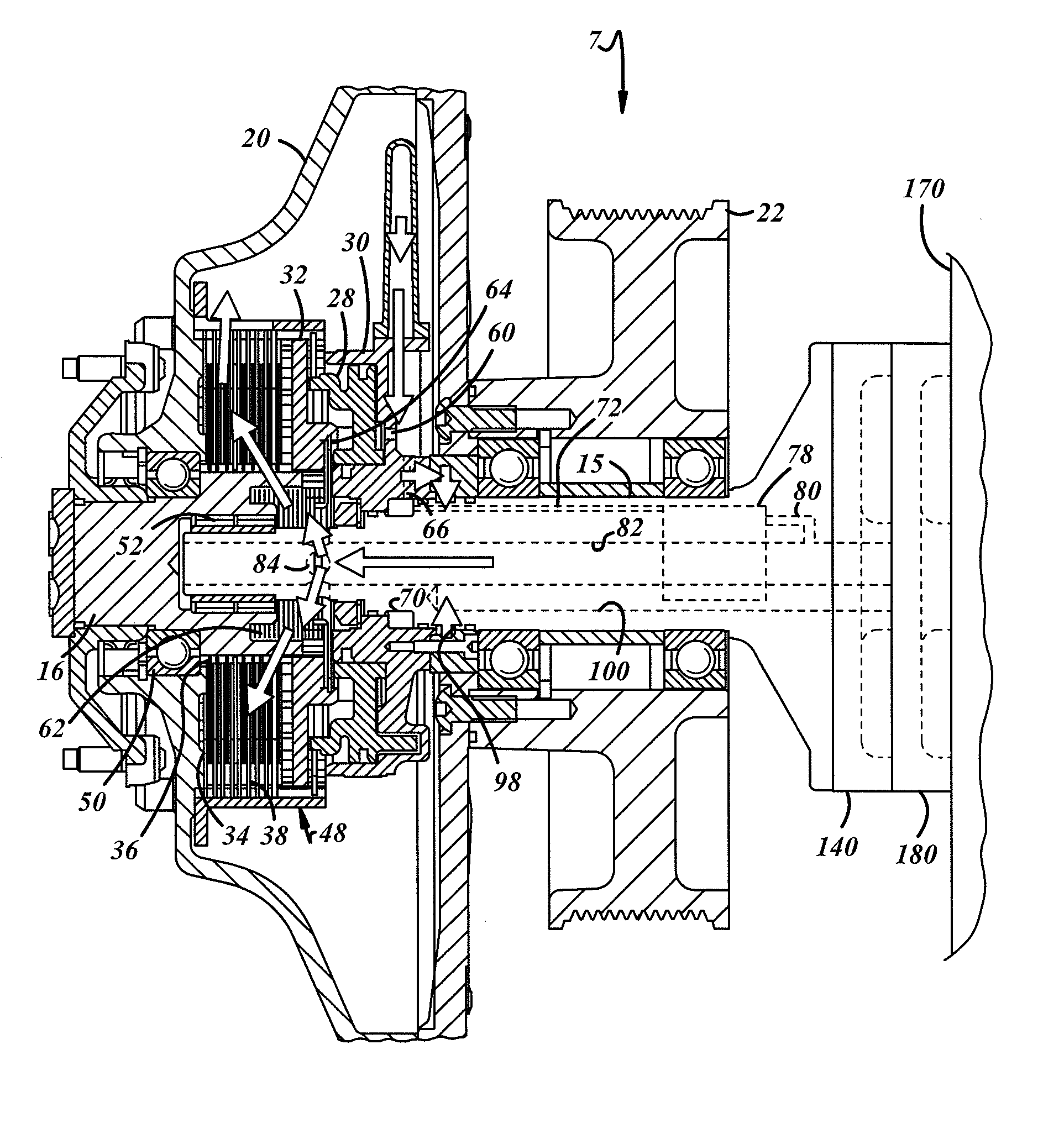
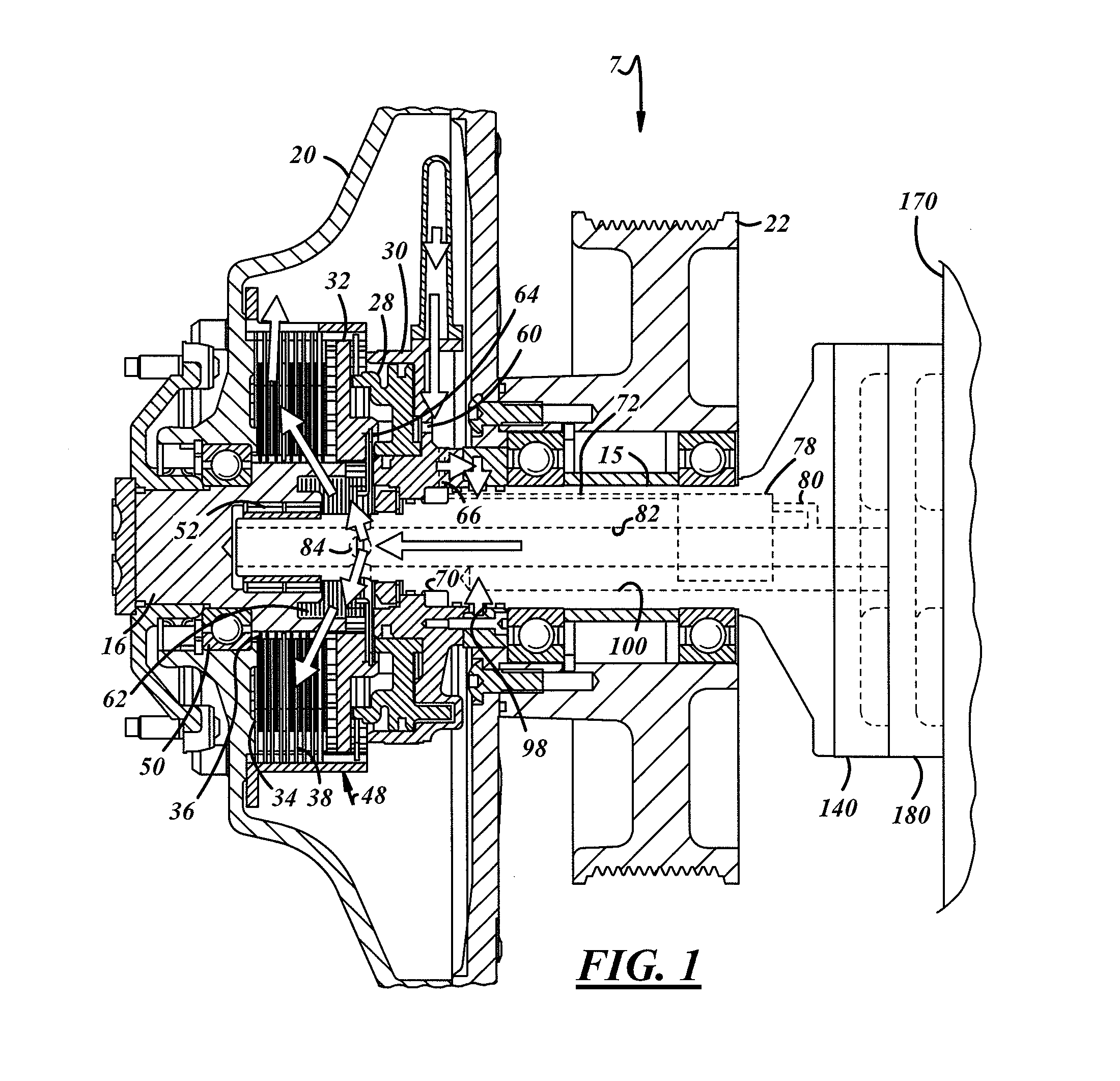
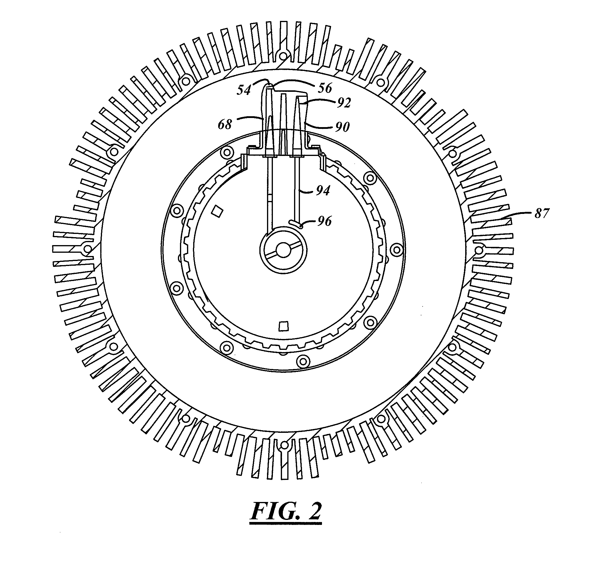
[0020]Referring now to FIGS. 1-6, a hydraulically controlled fan drive system 7 in accordance with an embodiment of the present invention is shown. The fan drive 7 uses rotational energy from a liquid cooled engine at an increased ratio to turn a radiator cooling fan (not shown) to provide airflow through a radiator (not shown). The system 7 includes a housing assembly 20 fixed to a pulley22, which is coupled to and rotates relative to a crankshaft (not shown) of the vehicle's engine, via a pair of belts (not shown), within an engine compartment (not shown). The present invention may be relatively operative in relation to various components and via any number of belts or other coupling devices, such as a timing chain. The housing assembly 20 is mounted on the vehicle's engine via a mounting bracket shaft 15. The housi...


PUM


Abstract

A fan drive system is provided having a housing connected with a pulley. A fan shaft is rotatably mounted to the housing by a clutch. A piston actuates the clutch. A pressure tube is provided for delivering pressure to the piston. A valve controls pressure against the piston. A fixed shaft rotatably supports the housing and the pulley and has passages extending through the pulley. A base connects the support shaft to a vehicle structure. An oil plate has inlets and outlets with the shaft passages. The oil plate circulates the hydraulic fluid. A coolant plate is juxtaposed between the oil plate and the structure supporting the support shaft. The coolant plate has inlets and outlets for coolant from a remote cooler.

Description

FIELD OF THE INVENTION[0001]The invention relates generally to fan drive systems that are hydraulically controlled with integral cooling.BACKGROUND OF THE INVENTION[0002]Friction coupling devices and fluid coupling devices that drive radiator cooling fans for over the road trucks, such as class 8 trucks, are generally of two types, dry friction clutch assemblies and viscous drives, respectively.[0003]Dry friction clutch assemblies tend to have two operating conditions “ON and OFF” referring to when a friction clutch is either fully engaged or fully disengaged. When a friction clutch assembly is providing cooling the clutch is fully engaged and not slipping. When the friction clutch assembly is not providing cooling the assembly is fully disengaged and slip speed is at a maximum between a clutch plate and an engagement surface.[0004]The dry friction clutch assemblies generally have low thermal capacity, since they typically do not incorporate fluid flow cooling mechanisms. Thus, the ...

Claims


Application Information

Patent Timeline
IPC IPC(8): F16D25/12F16D25/0635
CPCF01P7/042F16D25/082F16D25/123F16D25/06F16D2300/021F16D2500/10418F16D43/284
Inventor PICKELMAN, JR., DALE M.TEMBREULL, THOMASCOOPER, MICHAELCROCKETT, PAULHAGEDORN, MICHAELRUMAO, JUSTIN
Owner BORGWARNER INC
Why Eureka
Try Eureka