Light emitting diode with improved luminous efficiency

Active Publication Date: 2012-03-01
SEOUL VIOSYS CO LTD
View PDF10 Cites 59 Cited by
  • Summary
  • Abstract
  • Description
  • Claims
  • Application Information

AI Technical Summary

Benefits of technology

[0013]Exemplary embodiments of the present invention provide

Problems solved by technology

Generally, since the p-type semiconductor layer may have high specific resistance, electric current may not be evenly distributed in the p-type semiconductor layer, but may be concentrated on a portion of the p-type semiconductor layer having the P-electrode formed thereon, and may cause a problem of current crowding at an edge of the p-type semiconductor layer.
Current crowding may lead to a reduction in light emitting area, thereby deteriorating luminous efficiency.
However, despite excellent electrical conductivity of the transparent electrode layer, current crowding may occur near the electrode pad, and although the transparent electrode layer may induce some degree of reflection or refraction of light, optical loss may occur due to total internal reflection caused by a difference in refractive index between the transparent electrode layer and the exterior.
However, since the transparent electrode layer may absorb light, the thickness of the transparent electrode layer is limited, thereby providing limited current spreading.
In particular, in a large-scale LED having an a

Method used


Image

  • Light emitting diode with improved luminous efficiency
  • Light emitting diode with improved luminous efficiency
  • Light emitting diode with improved luminous efficiency

Examples


Embodiment Construction

[0037]The invention is described more fully hereinafter with reference to the accompanying drawings, in which exemplary embodiments of the invention are shown. This invention may, however, be embodied in many different forms and should not be construed as limited to the exemplary embodiments set forth herein. Rather, these exemplary embodiments are provided so that this disclosure is thorough and will fully convey the scope of the invention to those skilled in the art. In the drawings, the sizes and relative sizes of layers and regions may be exaggerated for clarity. Like reference numerals in the drawings denote like elements.

[0038]It will be understood that when an element such as a layer, film, region or substrate is referred to as being “on” another element, it can be directly on the other element or intervening elements may also be present. In contrast, when an element is referred to as being “directly on” another element, there are no intervening elements present.

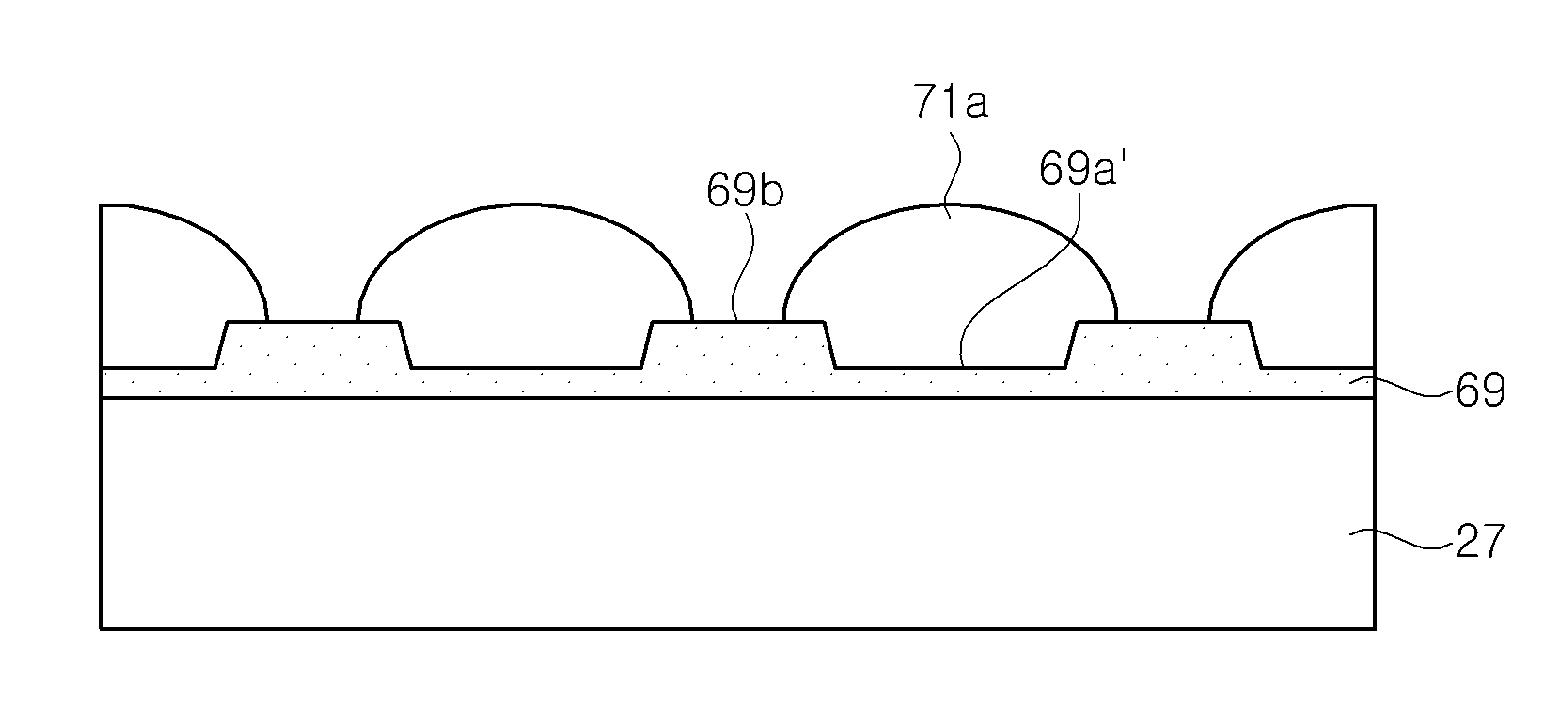
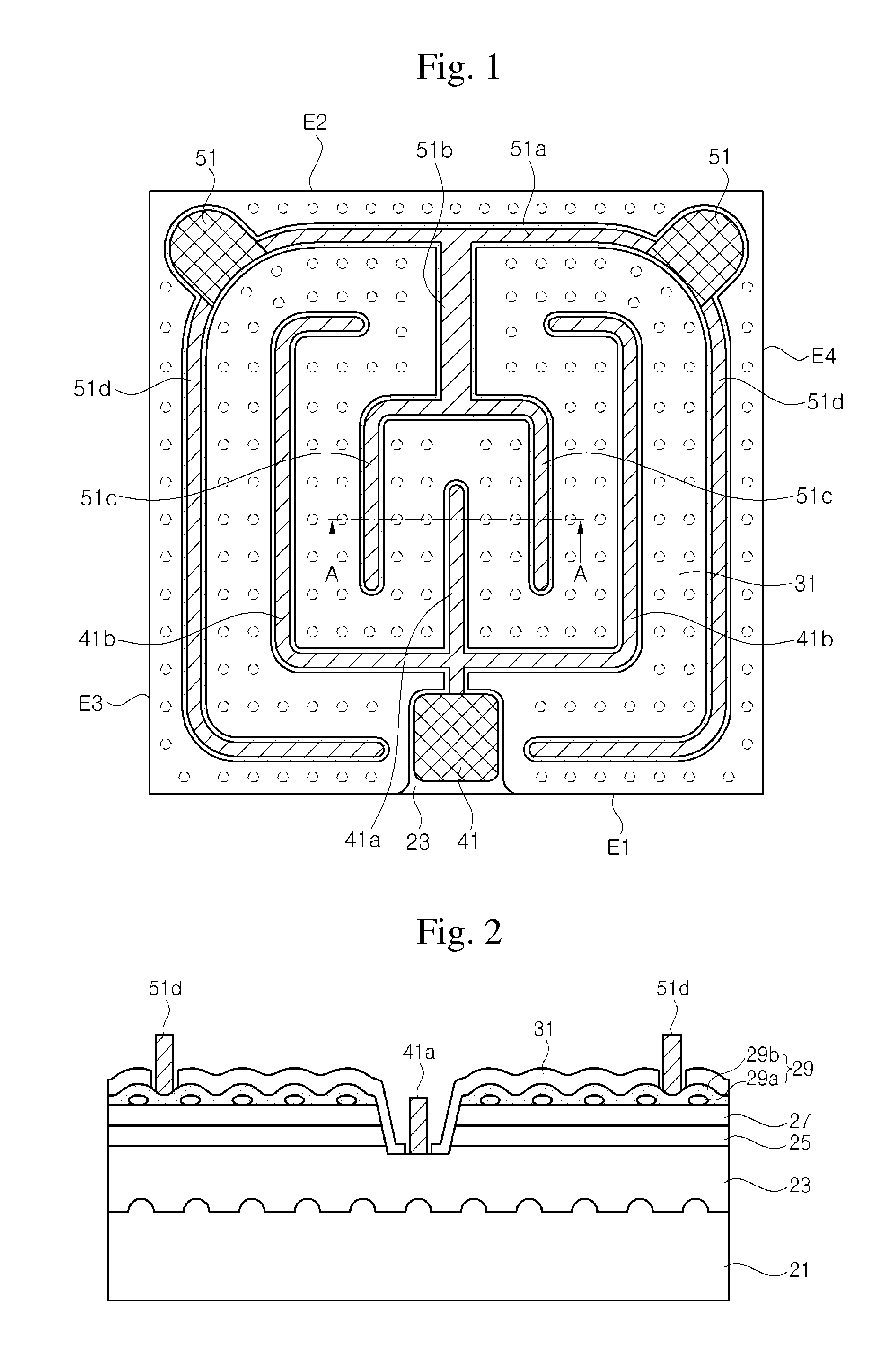
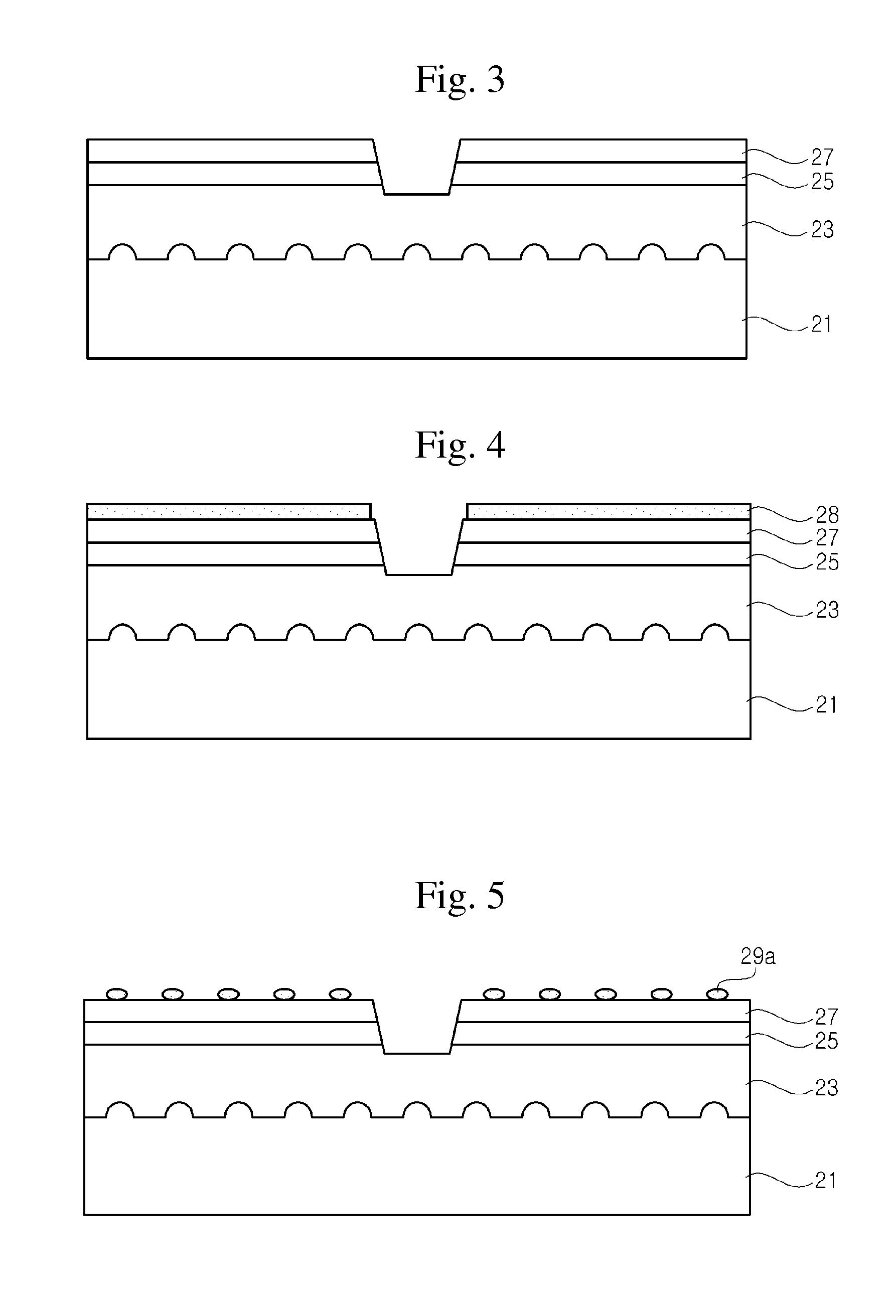
[0039]FIG. 1 ...


PUM


Abstract

Exemplary embodiments of the present invention relate to light emitting diodes. A light emitting diode according to an exemplary embodiment of the present invention includes a substrate having a first side edge and a second side edge, and a light emitting structure arranged on the substrate. The light emitting structure includes a first conductivity-type semiconductor layer, an active layer, and a second conductivity-type semiconductor layer. A transparent electrode layer including a concave portion and a convex portion is arranged on the second conductivity-type semiconductor layer. A first electrode pad contacts an upper surface of the first conductivity-type semiconductor layer and is located near a center of the first side edge. Two second electrode pads are located near opposite distal ends of the second side edge to supply electric current to the second conductivity-type semiconductor layer. A first pad extension extends from the first electrode pad and a second pad extension extends from each of the two second electrode pads.

Description

CROSS-REFERENCE TO RELATED APPLICATIONS[0001]This application claims priority from and the benefit of Korean Patent Application No. 10-2010-0083480, filed on Aug. 27, 2010 and Korean Patent Application No. 10-2010-0096016, filed on Oct. 1, 2010, which are hereby incorporated by reference for all purposes as if fully set forth herein.BACKGROUND OF THE INVENTION[0002]1. Field of the Invention[0003]Exemplary embodiments of the invention relate to light emitting diodes and, more particularly, to light emitting diodes with improved luminous efficiency.[0004]2. Discussion of the Background[0005]Gallium nitride (GaN) based light emitting diodes (LEDs) have been used in a wide range of applications including natural color LED display devices, LED traffic sign boards, white LEDs, etc.[0006]The GaN-based light emitting diode is generally formed by growing epitaxial layers on a substrate, for example, a sapphire substrate, and includes an n-type semiconductor layer, a p-type semiconductor laye...

Claims


Application Information

Patent Timeline
IPC IPC(8): H01L33/58H01L33/42
CPCH01L33/20H01L33/38H01L33/385H01L2933/0091H01L33/42
Inventor YANG, JEONG HEEKIM, KYOUNG WANYOON, YEO JINKIM, YE SEULOH, SANG HYUNSUH, DUK ILLEE, KEUM JULEE, JIN WOONGJEONG, DA YEON
Owner SEOUL VIOSYS CO LTD
Why Eureka
Try Eureka